Accessories
Cables
There are 4 Types of cables that are compatible with the Ouster sensors.
The cable and plug are an element of the sensor ingress protection. Without this, the ingress protection rating may be compromised.
Bending the cable at a sharp angle directly after the plug overmold should be avoided. Sharp bends and high axial stresses on the cable immediately adjacent to the plug overmold may create a moisture ingress path into the connection. Please note the cable minimum bend radius requirements here Cable Characteristics.
Note
Ouster recommends using a right angled connector cable for use cases wherein the cable needs to be bent within the first 5 cm between the connector and the rest of the cable.
The recommended cable bend radius is 5 x O.D (O.D = outer diameter of the cable) for applications where the cable is static, or non-moving. Please observe a minimum bend radius of 10 X O.D for installations where the cable is frequently moving.
Note
For Rev 06 and prior sensor, Ouster requires the users to use Type 3 cables with Zinc connectors. For Rev6.2 and later sensors, use Type 3 cables with Stainless Steel connectors. If you need 1000BASE-T1 Single-Pair Ethernet (SPE), use Type 4 cables.
We no longer offer Type 1 and Type 2 cables for sale. Please contact Ouster sales for questions regarding available cable lengths, connector types, and termination options.
Warning
User must make sure to use a zinc connector cable if the sensor has a zinc connector on it, a stainless steel connector cable if the sensor has a stainless steel connector on it. If you have any questions regarding the type of cable or connector you have please contact Ouster Support.
Cable Characteristics
Note
Type 4 (1000BASE-T1) is only applicable for Rev7 (OS0, OS1 and OSDome) Sensors, please use this section only for reference as this is not available for Rev7 OS2 sensor.
Cable |
Outer Diameter |
Cable Minimum Bend (Static) |
Cable Minimum Bend (Flexible) |
Type 1 (Thick) |
10.5mm |
79mm |
158mm |
Type 2 (Thin) |
8mm |
40mm |
80mm |
Type 3 ( |
8.2mm |
41mm |
82mm |
Type 4 ( |
7.5mm |
37.5mm |
75mm |
Note
Type 3 Cable has an imprint that states “Type 3” on it whereas, Type 2 & Type 1 do not have any identifiers.
Electrical Characteristics (POWER and GROUND wires)
Ouster has characterized the cable resistance and contact resistance of our cables at room temperature. This can be found below:
Cable |
Maximum Cable Resistance (Ω/m) |
Typical End to End Resistance for 5m Cable (Ω) |
Admissible Nominal Operating voltage (V) |
Type 1 (Thick) |
0.110 |
0.45 |
24 |
Type 2 (Thin) |
0.110 |
0.45 |
24 |
Type 3 ( |
0.042 |
0.3 |
9 - 34 |
Type 4 ( |
0.042 |
0.3 |
9 - 34 |
For full sensor functionality, a minimum of 9.0 V must reach the sensor and the maximum allowed operating voltage is 34 V. To compensate for losses through wire resistance, a higher voltage must be provided to the interface end of the cable, which may be the Interface Box or the pigtail wires. If the sensor is below this voltage for at least 1 second, the INPUT_VOLTAGE_LOW error will be triggered.
The following graph Voltage at connector vs cable length can be used as a guide to determine the appropriate input voltage to the sensor connector for your desired cable length. The values on the graph were calculated using idealized cable resistances derived from the AWG system and assumed maximum power draw from the sensor.
Note
For Type 4, please refer to Type 3 (18 AWG) in the graph below as they have the same electrical characteristics.
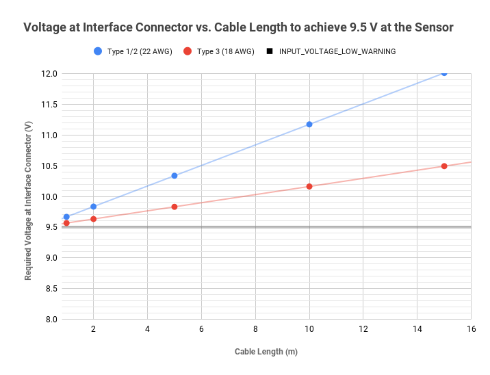
Voltage at connector vs cable length
Interface Box
All Interface Boxes are provided with a DC power port and an RJ45 jack for Ethernet. Currently Ouster offers two types of Interface boxes to support both 12V and 24V.
Legacy 24V nominal Interface Boxes provided with Type 1 and Type 2 cables are assembled with integral cables for connection to Ouster’s sensors.
12V/24V nominal Interface Boxes with Type 3 cables are provided in modular and integral cable variants. The modular variant has a built-in connector and a detachable double-connectorized Type 3 cable for connection to Ouster’s sensors. Whereas, the integral cable variant which is our current “STANDARD” are not detachable and have only one sided connector. Both variants have a GPS connector capable of accepting TTL level signals originating from a separate GPS device that contains ESD protection circuitry.
Note
Both Legacy and Modular interface boxes are no longer available for purchase, it has been mentioned in this user manual for reference/information only for existing users. Please contact Ouster sales representative for questions regarding available options.
Example: GPS Module compatible with Ouster Sensor GPS Module. If you need support to configure the GPS to works with our sensor please contact Ouster Support.
Warning
RISK OF FIRE OR ELECTRIC SHOCK. DO NOT CONNECT THE GPS CONNECTOR DIRECTLY TO AN ANTENNA.
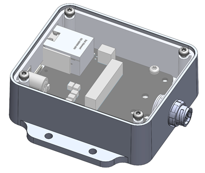
Interface Box – Important Notice
The Ouster Interface Box is a support tool for use in laboratory environments to assist customers in evaluating Ouster’s lidar sensor products and in the development of software. The Interface Box is not protected from ingress of moisture or solid particles and is not intended for use outdoor.
The Interface Box has a top cover affixed using 4 self-tapping screws. The cover may need to be removed in order to set the operating modes or to change the fuse. The plastic that the self-tapping screws fasten into is delicate, please remove and replace the screws slowly and carefully. When multiple attempts are made to remove the screws, the mounting posts may be stripped.
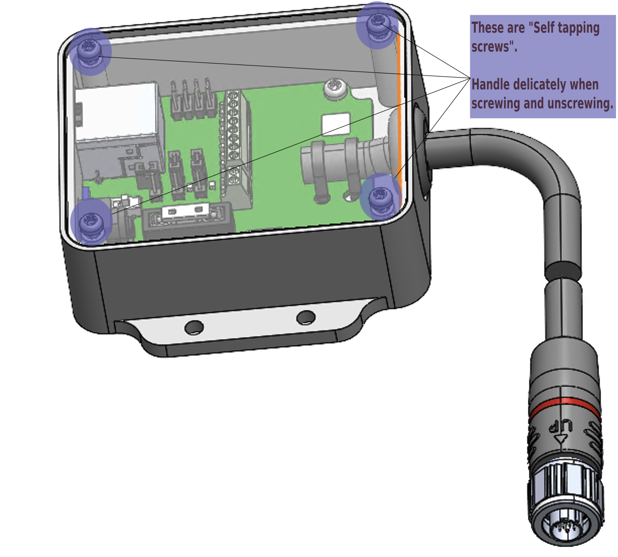
Warning on Self Tapping Screws
Types and Physical Characteristics
A list of all Ouster provided interface boxes are provided for reference below. Please contact Ouster Support if you have any further questions.
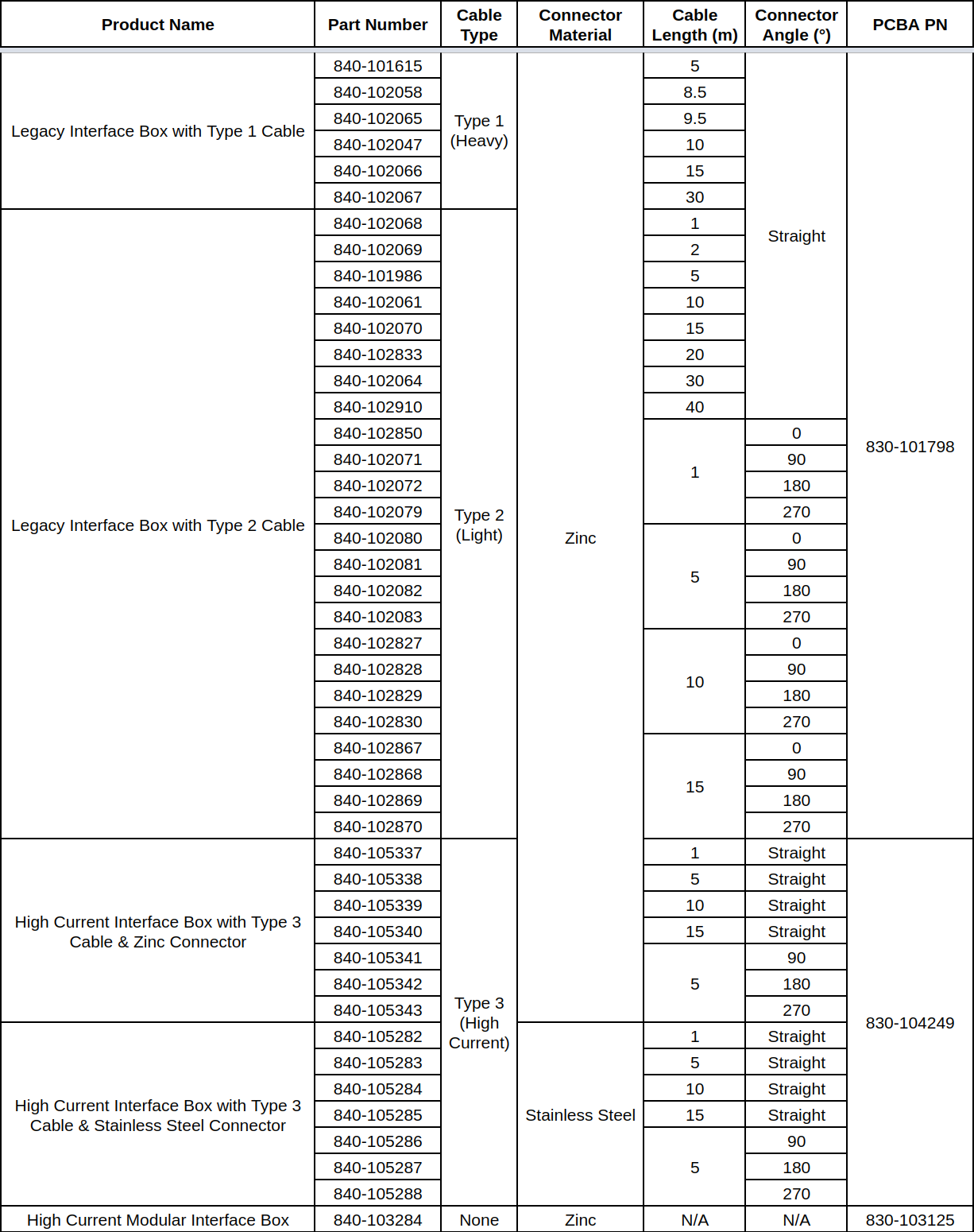
Types of Interface Boxes
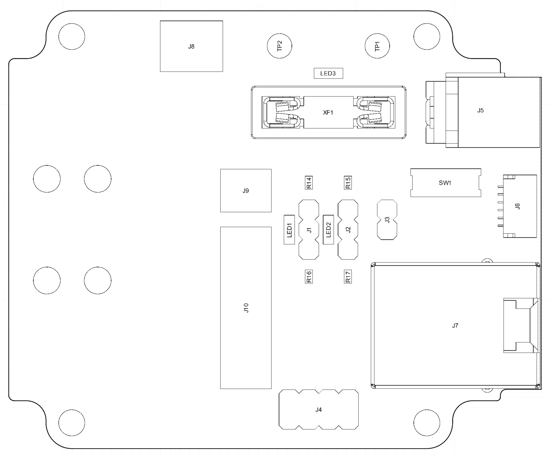
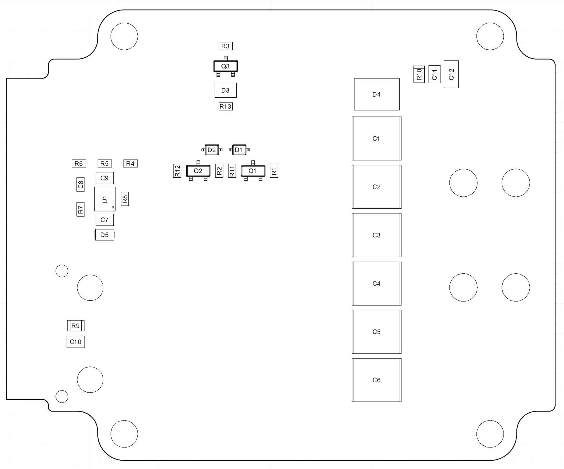
High Current Interface Box (PCBA 830-104249) - Standard
This is a 12V/24V nominal Interface Box with Type 3 cable available with either zinc or stainless steel connectors. This interface box has a GPS connector capable of accepting TTL level signals originating from a separate GPS device that contains ESD protection circuitry.
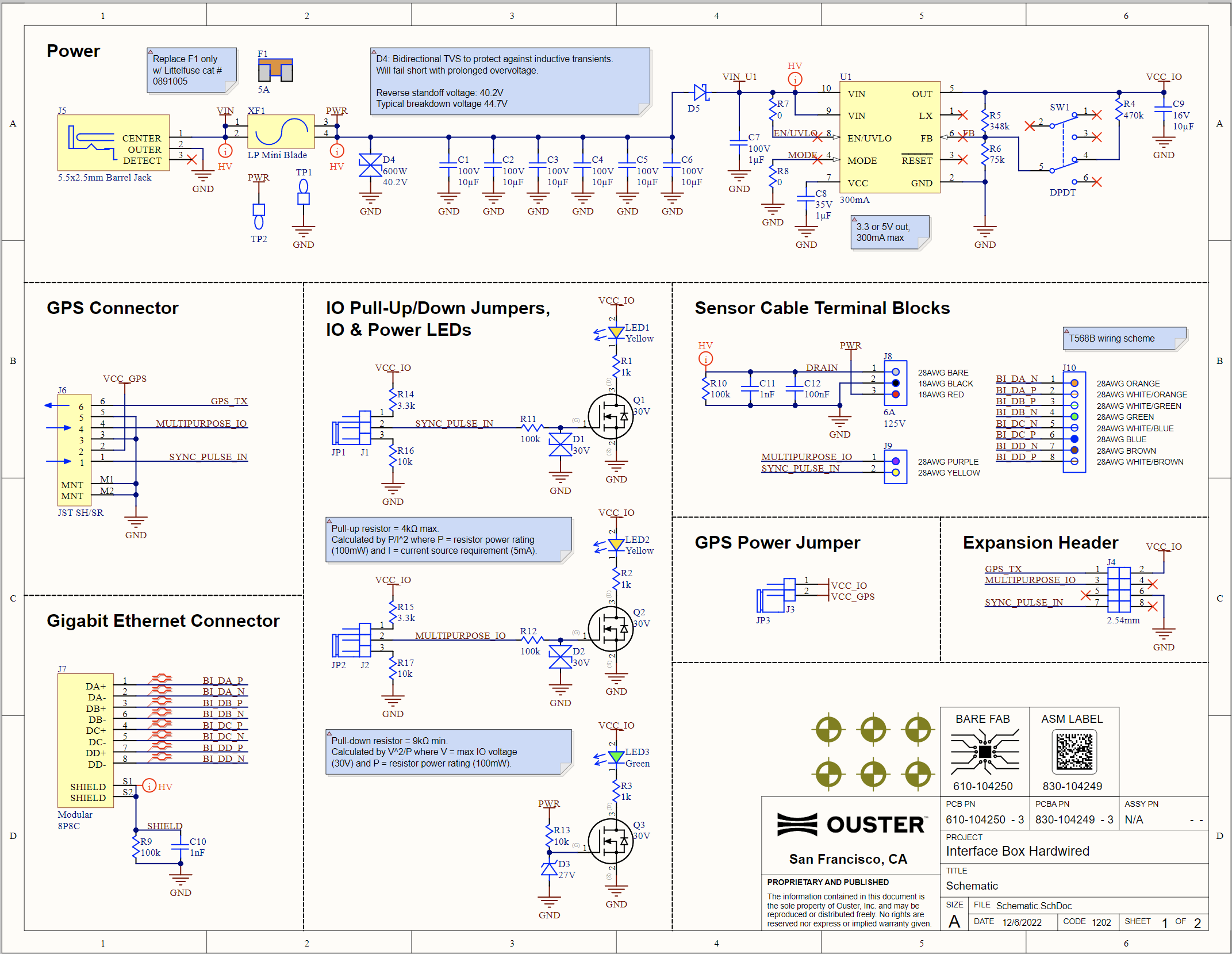
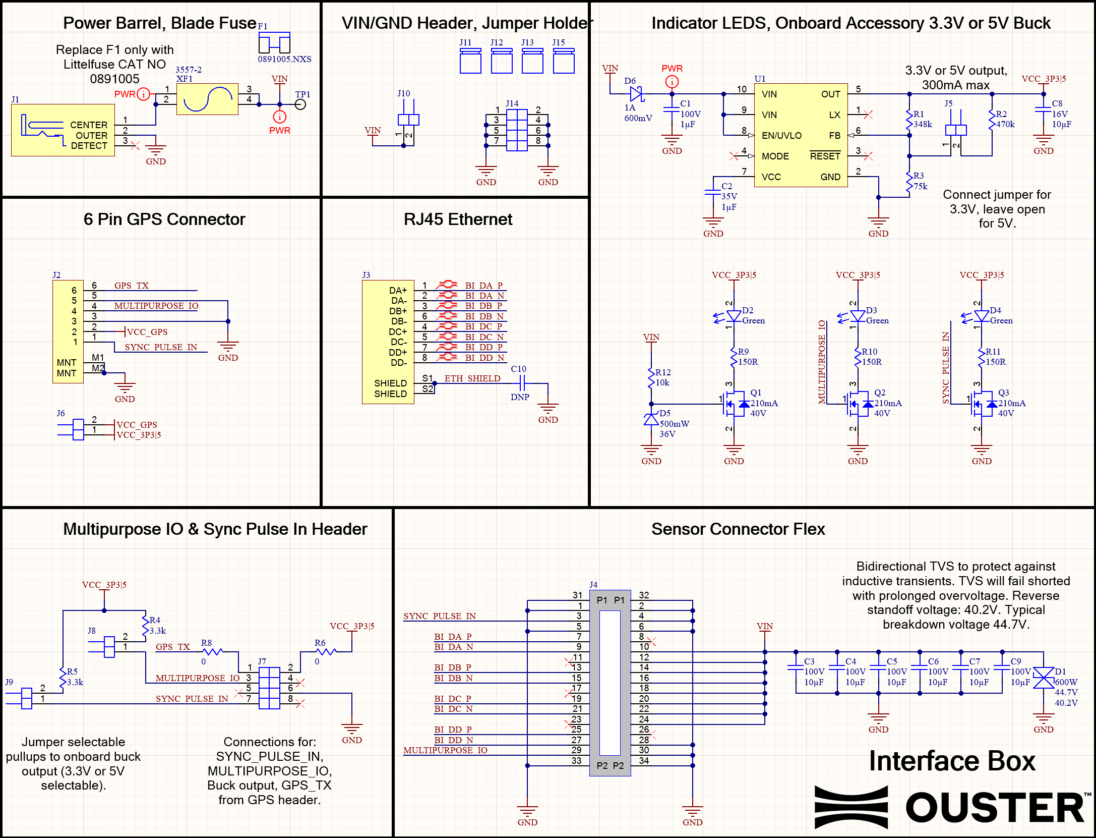
Interface Box Schematic Diagram
Cable Connection and Pinout
Ouster sensors can be operated without the use of an Interface Box. For more information on the Ouster Cable Pinout please refer to Direct Cable Connection and Pinout.
Front pane |
Rear Pane |
Specification
Gigabit ethernet RJ45 jack (1000BASE-T).
VIN Barrel Jack. Use with a 5.5mm OD x 2.5mm ID barrel plug.
User replaceable 5A fuse. Use only
Littlefuse #0891005.VIN green LED indicator.
Onboard buck power supply generating VCC_IO. VCC_IO supplies the onboard LEDs and pullups, and is user accessible via headers J3 & J4. Switch SW1 is used to select the buck’s output voltage. WARNINGS: Max allowable user consumption is 210mA. Ensure power to the Interface Box is disconnected when changing buck output voltage via SW1.
10kΩ pull-downs, 3.3kΩ pull-ups to VCC_IO, and yellow LED indicators for SYNC_PULSE_IN and MULTIPURPOSE_IO. Install a jumper on the respective header (J1 or J2) to enable the pull-down or pull-up.
0.1” pitch, 4x2 pin header J4. GPS_TX (Pin 1) is only connected to connector J6; it is not connected to the sensor.
6-pin JST SH/SR connector J6. VCC_GPS (Pin 2) is connected to VCC_IO by installing a jumper on header J3. GPS_TX (Pin 6) is only connected to header J4; it is not connected to the sensor.
High Current Modular Interface Box (PCBA PN- 830-103125)
This type of interface box is designed for users who require the use of a lower voltage power supply, such as 12V (as long as the sensor also supports a wide input voltage range). These interface boxes also have a new GPS input connector capable of accepting TTL level signals that originate in a separate GPS device that contains an ESD dissipation circuit.
Interface Box 12V Design |
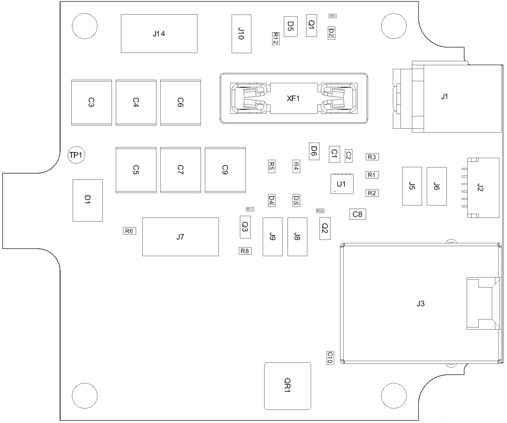
Modular Interface Box Connection Diagram (PCBA PN- 830-103125) |
Modular Interface Box Schematic Diagram
Specification
Gigabit ethernet RJ45 jack (1000BASE-T).
VIN Barrel Jack. Use with a 5.5mm OD x 2.5mm ID barrel plug.
User replaceable 5A fuse. Use only
Littlefuse #0891005.VIN green LED indicator, fuse-protected VIN header (J10) and Ground header / jumper storage (J14).
Onboard buck power supply generating VCC_3P3|5. VCC_3P3|5 supplies the onboard LEDs and pullups, and is user accessible via headers J2 & J7. Header J5 is used to select the buck’s output voltage: install a jumper for 3.3V, leave open for 5V. WARNINGS: Max allowable user consumption is 210mA. Ensure power to the Interface Box is disconnected when changing buck output voltage via J5.
3.3kΩ pullups to VCC_3P3|5 and green LED indicators for SYNC_PULSE_IN and MULTIPURPOSE_IO. Install a jumper on the respective header (J9 or J8) to enable the pullup.
0.1” pitch, 4x2 pin header J7. GPS_TX (Pin 1) is only connected to connector J2; it is not connected to the sensor.
6-pin JST SH/SR connector J2. VCC_J2 (Pin 2) is connected to VCC_3P3|5 by installing a jumper on header J6. GPS_TX (Pin 6) is only connected to header J7; it is not connected to the sensor.
Note
This interface box is no longer available for purchase and is specified in this manual only for reference for existing users. This is optional for Rev 06 Sensors and above and is compatible with Type 3 double-ended Cables only.
Interface Box 24V (Legacy Type 1 and Type 2)
For more information on this please refer to Rev 06 or prior Hardware User Manuals.

Sensor-Interface box connectivity
Note
Ouster no longer offers Type 1 & Type 2 cables. Please contact Ouster sales for questions regarding available cable types, lengths, connector types, and termination options.
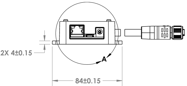
Connectors
Connectivity Guide:
8P8C “RJ45” Jack: Gigabit ethernet connection
6-Pin JST SH/SR: Connector for external GPS
5.5 x 2.5mm Barrel Jack: DC power input
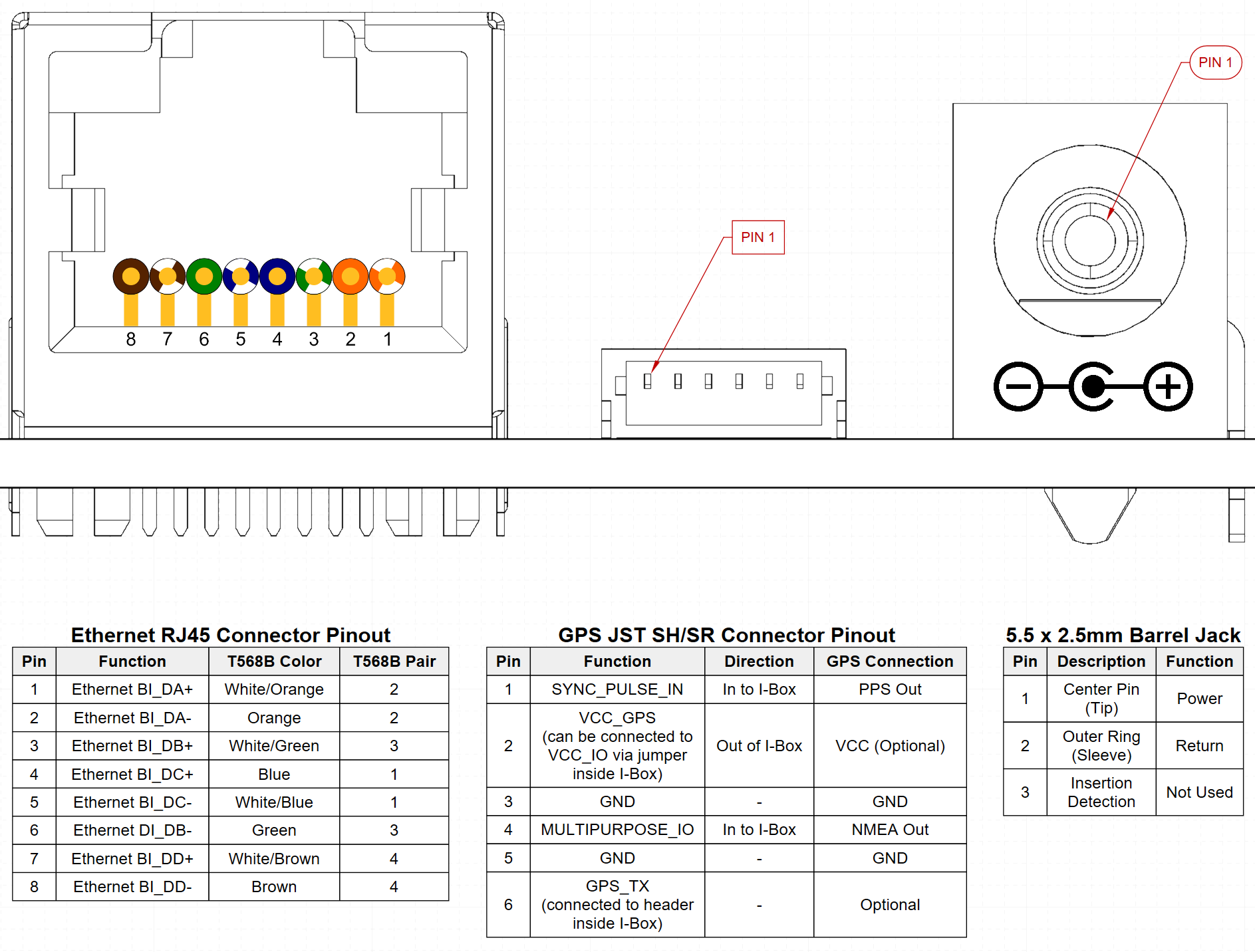
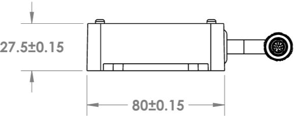
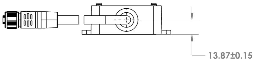
Connector Outline
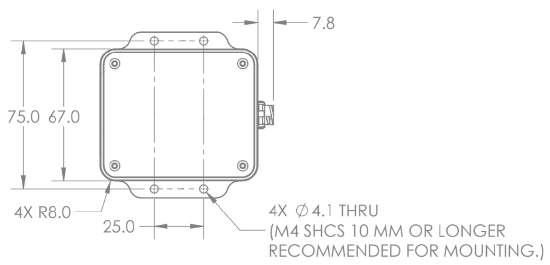
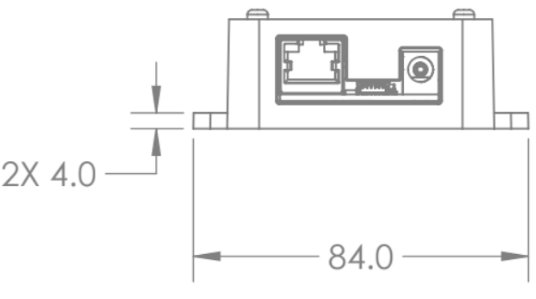
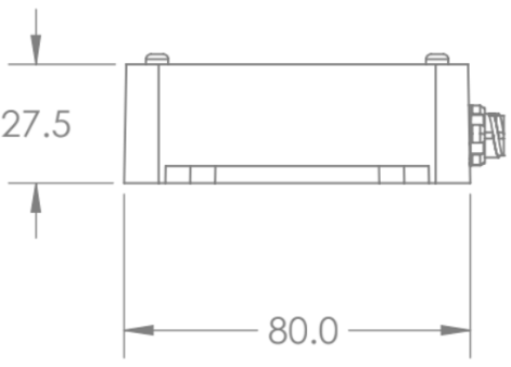
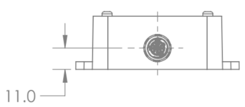
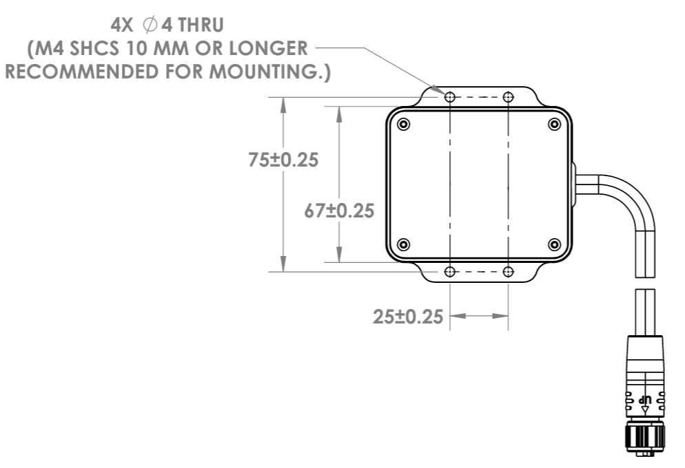
Mounting Interface Box
The interface box may be mounted on a table top or on a wall (or similar vertical surface). Use not less than two (2) screws (M4 SHCS 10mm or longer are recommended) to secure the interface box to the mounting surface.
High Current Modular Interface Box (PCBA PN- 830-103125)
|
|
|
|
Note
This type of interface box is NO longer available for purchase and are specified in this document for reference only for users who already have them.
High Current (12 or 24V) Interface Box (PCBA 830-104249) - Standard
|
|
|
|
For more information on Ouster sensor CAD files refer to Downloads page.
Electrical Characteristics
High Current Interface Boxes are rated 12VDC, 3.3A and 24VDC, 1.1A. They support 24V operation on all Ouster sensors, and 12V operation for Rev5 and above sensors only.
Legacy Interface Boxes are rated 24VDC, 1.1A and supports all Ouster sensors.
Over-current Protection
High Current Interface Boxes contain a user replaceable 5A low-profile mini blade fuse. When replacing this fuse, use only a Littelfuse #0891005 fuse. Use of any other fuse may lead to a risk of fire.
Legacy Interface Boxes are provided with thermistor type over-current protection to supplement the internal over-current protection in the sensor. The thermistor is soldered in place and is not user replaceable.
Power Supply
The Interface Box ships with a 24VDC 1.5A power supply and a cord set suitable for use in the U.S.A and Canada. High Current Interface Boxes are able to operate from a 12VDC source, but a 12VDC power supply is not provided by Ouster.
Legacy Interface Boxes are only designed for use with the supplied 24V power supply.
To select a power supply, it should:
have a 12VDC output voltage rating.
be capable of delivering at least 3.3A.
be identified or marked as having a Limited Power Source (LPS) output.
be safety certified by an acceptable test house in the local region of use using either IEC 60950-1 or IEC 62368-1 (or the EN or other national equivalent).
be provided with a power supply cord set appropriate for the power supply’s input and the socket outlets available in the lab space.
be provided with a standard 5.5 x 2.5mm center-positive barrel connector.

Power Supply
Selecting a Power Supply Cord/Cord-set
If purchasing a power supply locally, it should be supplied with an appropriate power supply cord or cord-set for use with the power supply.
If it’s necessary to select a power supply cord-set for the Ouster supplied power supply, it should be safety certified by a test house acceptable to the local region of use, supplied with an IEC 60320, Type C6 cord connector to mate with the power supply and a plug for connection to an AC outlet with an earthing contact/pin.
Environmental Ratings
All Interface Boxes are suitable for use indoors only in clean, protected environments at temperatures between -20 °C and +50 °C. Interface Boxes are not designed for use outdoors or in environments that are not protected from dust, moisture, or high humidity.