Quick Start Guide
This Firmware User Manual is meant to allow the users to take advantage of all the features that are available with Ouster Sensors. Detailed Instructions regarding lidar operations, lidar data, API Guides and Troubleshooting guide are present in this user manual.
For information on the mechanical and electrical operations or the interface box, please refer to the Hardware User Manual.
To know more about Ouster sensors and their specifications please refer to the datasheets available on our Website.
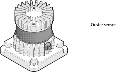
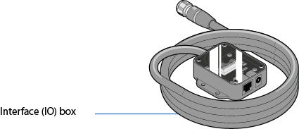
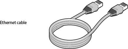
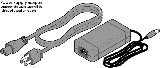
What’s in the box
|
|
|
|
Note
Interface box is not always shipped with the sensor, based on customer requirement it could be a pig tail connector cable or a custom cable.
Sensor Setup
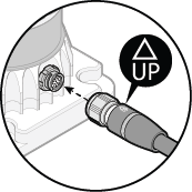
Connect one end of the bayonet-style connector to the Ouster sensor as shown. Verify that the plug “UP” indicator is pointed up.
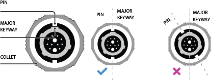
Rotate the collet on the plug until one of its two pins is aligned with the major keyway. This will allow its two pins to enter the receptacle channel.
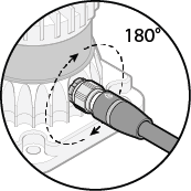
Connect the plug to the sensor, then rotate the collet 180 degrees clockwise until it clicks, this indicates that it is fully seated. Ensure the red line on the stainless steel connector collet is aligned with the emblem on the top of the overmold. This alignment confirms that the connector is properly locked.
Connect one end of the power supply to the wall socket and the other end to the IO box.
Connect one end of the ethernet cable provided to the IO box and the other end to a PC/LINUX/MAC user interface.
Network Configuration
The sensor is designed to communicate with a host machine through a variety of different methods such as DHCP, IPv6/IPv4 link-local, and static IP.
On most systems you should be able to connect the sensor into your network or directly to a host machine and simply use the sensor hostname to communicate with it.
Your Ouster sensor requires a computer with a gigabit Ethernet connection and a 24V supply.
Optionally you may time synchronize the sensor through an external time source or through the computer via PTP.

Network Configuration and Setup
The sensor hostname is os-991234567890.local, where 991234567890 is the sensor serial number. The sensor serial number can be found on a sticker affixed to the top of the sensor.
For more detailed guidance on communicating with the sensor on various operating systems and network settings please reference the Networking Guide in the Appendix.
Commands for setting and deleting a static IP address can be found in the HTTP API Reference Guide section.
Note
May be required to configure the firewall to connect with the sensor and access sensor data.
Open Google Chrome/Microsoft Edge/Firefox. Use the hostname in the format of http://OS-99xxxxxxxxxx.local and click on “Enter/Character turn” to open Ouster Dashboard.
Note
The serial number of the sensor need not start with
99and is only taken as an example in this document, the sensor serial number can be found on a sticker affixed to the top of the sensor.Please keep in mind NOT to use
https://as it will result in an error, use withoutsas shownhttp://OS-99xxxxxxxxxx.local.
Sensor Web Interface
The sensor homepage can be accessed by typing in the sensor’s address (IPv4, IPv6, or hostname) in a web browser (http://os-991234567890.local/ where 991234567890 is the serial number). From here you can see information about the sensor, access documentation, and configure sensor settings.
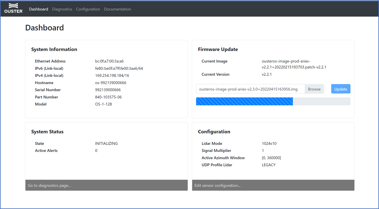
Dashboard: Contains an overview of the sensor.
System Information: This panel provides information regarding the network configuration and hardware details that are unique to each sensor
Firmware Update: You can update firmware on this panel. See Updating Firmware for more details.
System Status: This panel displays the status of the sensor and information regarding any Active Alerts. More information on the status of the sensor can be found by clicking the link, which will take the user to the Diagnostics tab.
Configuration: An overview of the sensor configuration is available on this panel. The sensor configuration can also be edited by clicking on the link below, which will take the user to the Configuration tab.
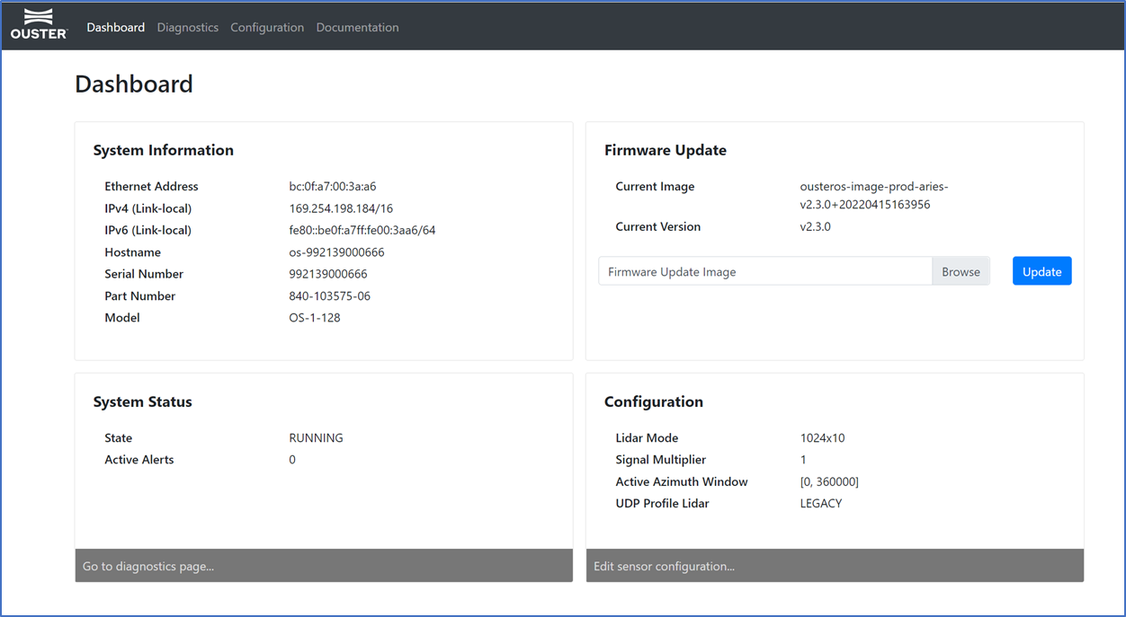
Ouster Dashboard
Diagnostics: Contains diagnostic alert and error information about the sensor for troubleshooting purposes. For a list of possible alerts and errors, see Alerts and Errors. Some Alerts require the user to reach out to Ouster support. Please include a copy of the System Diagnostics file which can be downloaded by clicking the blue tab on this page.
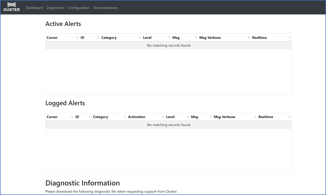
Ouster Alerts & Diagnostics
Configuration: This tab contains a user interface to change sensor configuration. If the sensor is in STANDBY mode, changes to configuration settings will not take effect until we switch the sensor back to NORMAL mode. Please refer to figure 3.4 for reference.
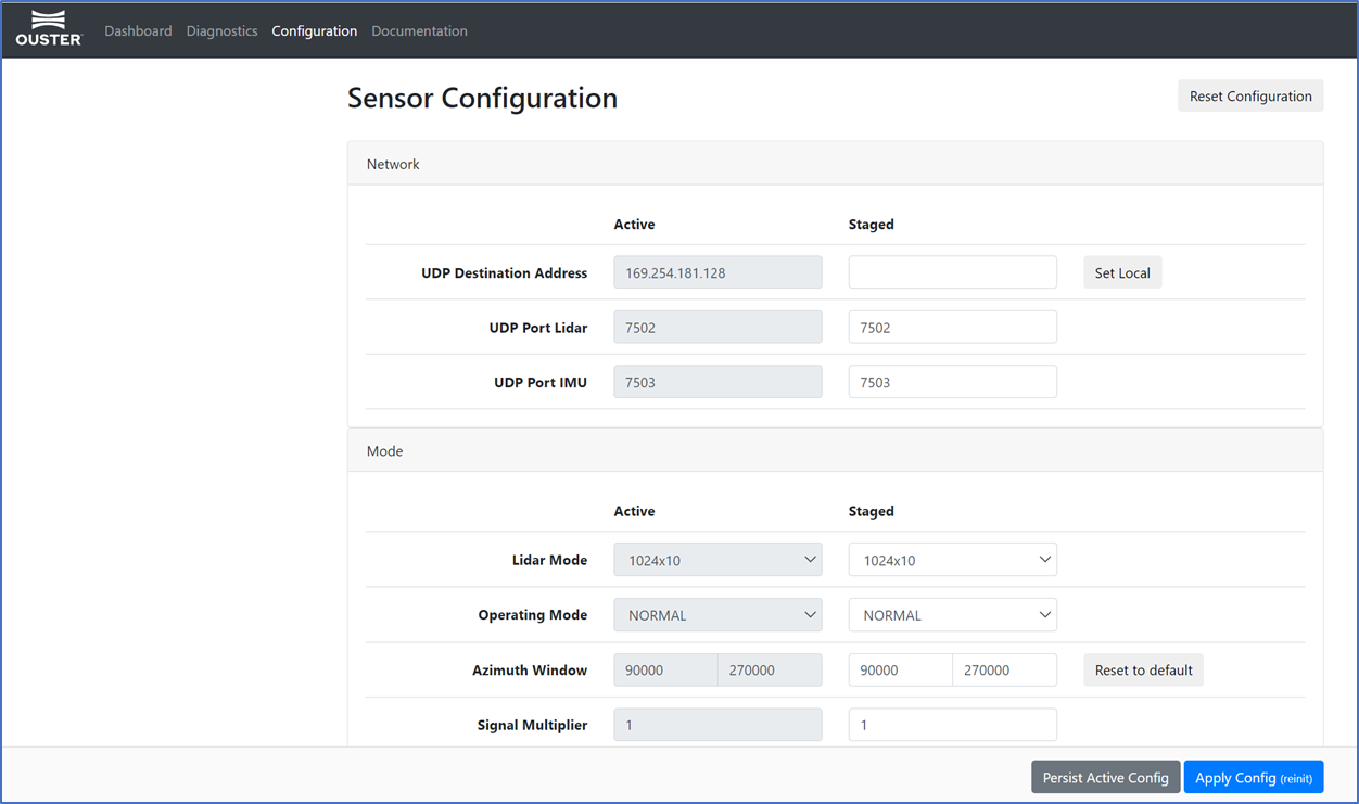
Sensor Configuration
Reset Configuration: Resets sensor to factory configurations and settings. Note that this resets any static IP address given to the sensor.
Persist Active Config: Stores the currently active sensor configuration to persistent storage so it will be reloaded whenever the sensor starts up.
Apply Config (reinit): Allows the user to configure the sensor settings. This involves a reinitialization of the sensor, so that the sensor configuration settings can take effect.
Documentation: Contains the HTTP and TCP API guides that are compatible with the version of the firmware on the sensor. Visit Ouster Sensor Documentation for latest hardware and software user manuals, along with integration guides and troubleshooting guides. Please refer to figure 3.5 for reference.
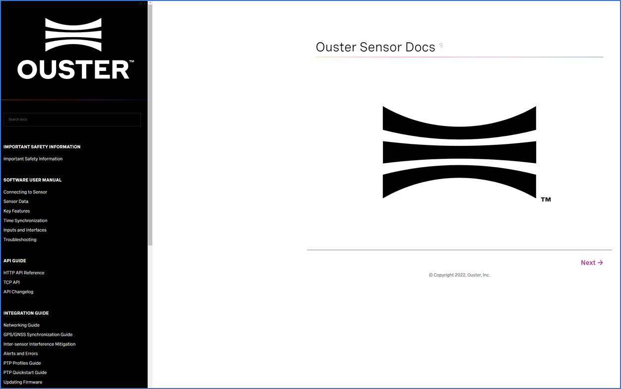
Ouster Documentation
Updating Firmware
Sensor firmware can be updated with an Ouster-provided firmware file from Ouster firmware by accessing the sensor over http - e.g., http://os-991900123456.local/ and uploading the file as prompted.
Note
User can also choose to do this step using an HTTP endpoint. Please refer to POST /api/v1/system/firmware in HTTP API section.
Uploading a new firmware image onto the sensor
Always check the firmware version running on the sensor before attempting to update. Only update to an equal or higher version number.
After the web UI confirms that the update is complete, please allow the sensor to reboot (about 2 minutes) and refresh your webpage to get access to the updated web UI.