OSDome - Rev7
Overview
The OSDome offers an industry-leading combination of price, performance, reliability, size, and weight. It is designed for indoor/outdoor all-weather environments and a long lifetime.
The OSDome family of sensors consist of three models, the OSDome-128, OSDome-64, and OSDome-32, with differing vertical resolution, but identical mechanical dimensions.
For the purposes of this document, the term “OS0” refers to the family of sensors, and only where there is a difference in performance will each model be referred to by its specific model designation.
The contents of this manual are applicable only to Rev7 sensors. Please find the sticker on the bottom of the sensor that will have all the information regarding product type, serial number and part number. For all other sensor hardware revisions, please refer to their respective hardware user manual.
OSDome Product Models
The OSDome is available with 128, 64, or 32 beams of vertical resolution and with Uniform, Gradient, Above Horizon, or Below Horizon beam spacing options. Product specs and more information on these configurations can be found on the OSDome product page.
Included Components
The OSDome is shipped with the following items:
Sensor
Interface box cable/connector
24V AC/DC power supply (2 meters)
RJ45 cable (1 meter)
Baseplate Mount
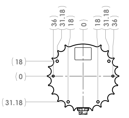
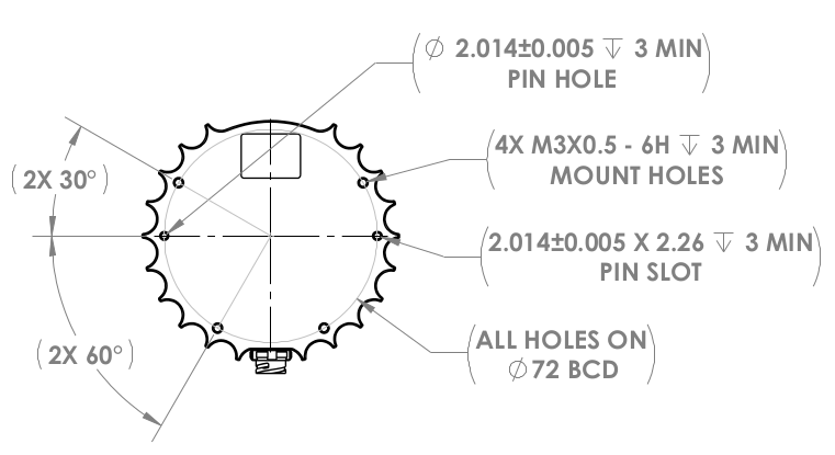
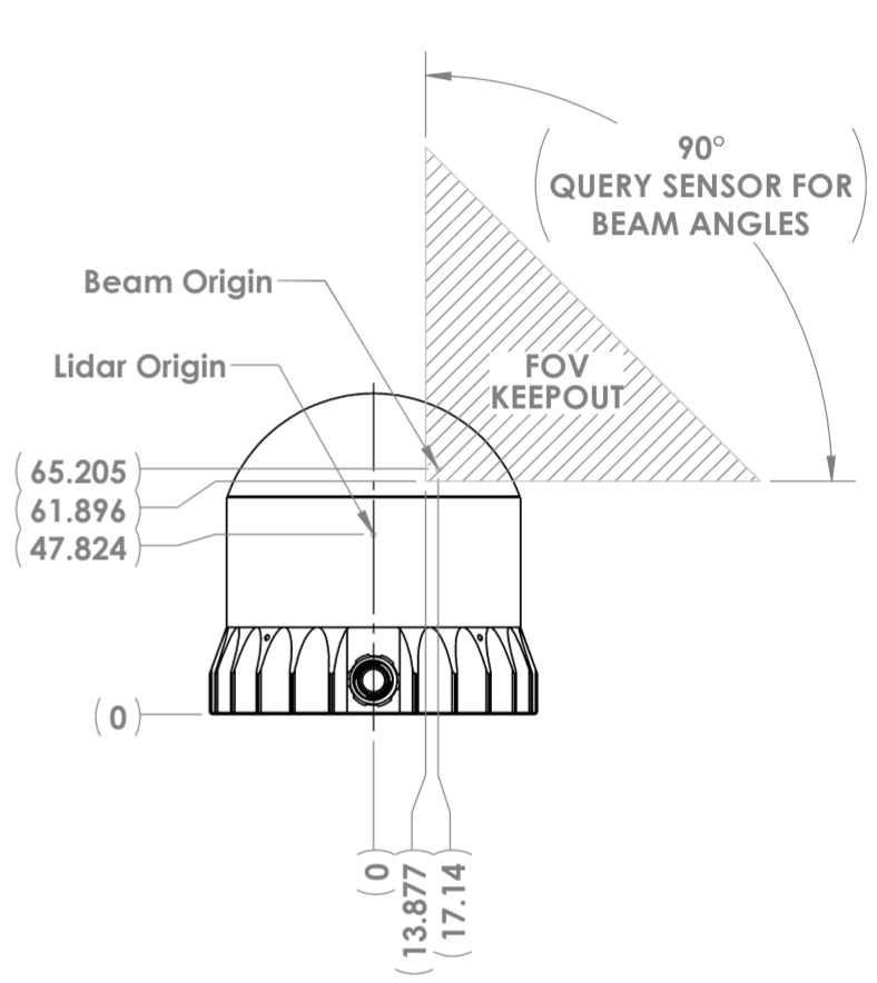
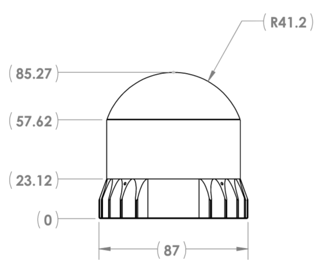
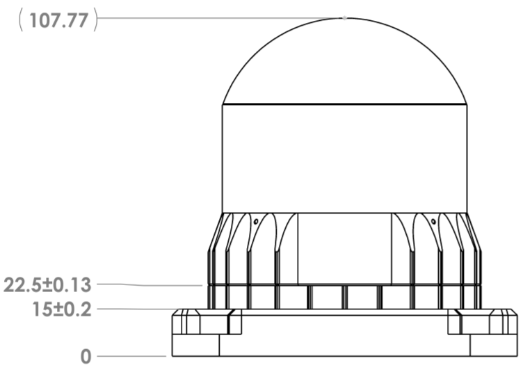
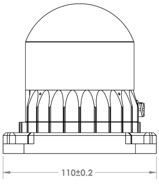
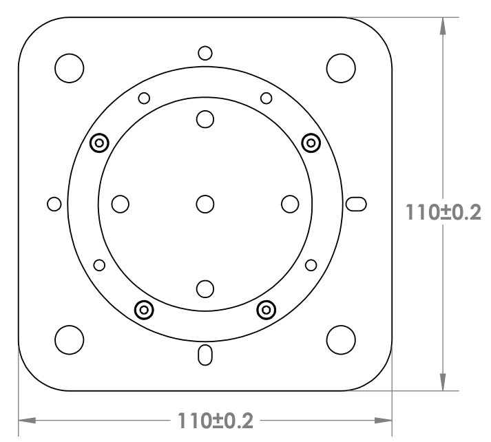
Mechanical Drawings
|
|
|
|
|
|
|
Downloadable CAD files for the OSDome can be found online at Ouster Download Page
Warning
The water ingress protection rating for the sensor is only valid if the I/O cable is plugged into the panel mount connector on the base of the sensor, and the locking collet rotated to the properly locked condition. The cable and plug are an element of the sensor ingress protection system. Without the connected cable the ingress protection rating may be compromised. Bending the cable at a sharp angle directly after egress from the plug over mold should also be avoided. Sharp bends and high axial stresses on the cable immediately adjacent to the plug over mold may create a moisture ingress path into the connector. Please refer to Cable Characteristics for more information on minimum bend radius requirements.
Mounting Guidelines
Our sensors ship with modular mounting options. The sensor can be mounted in any orientation except mounting from the top side of the sensor, some examples for OSDome Mounting Orientation (Examples) are shown below. Proper mounting will ensure optimal sensor performance and efficient heat dissipation.
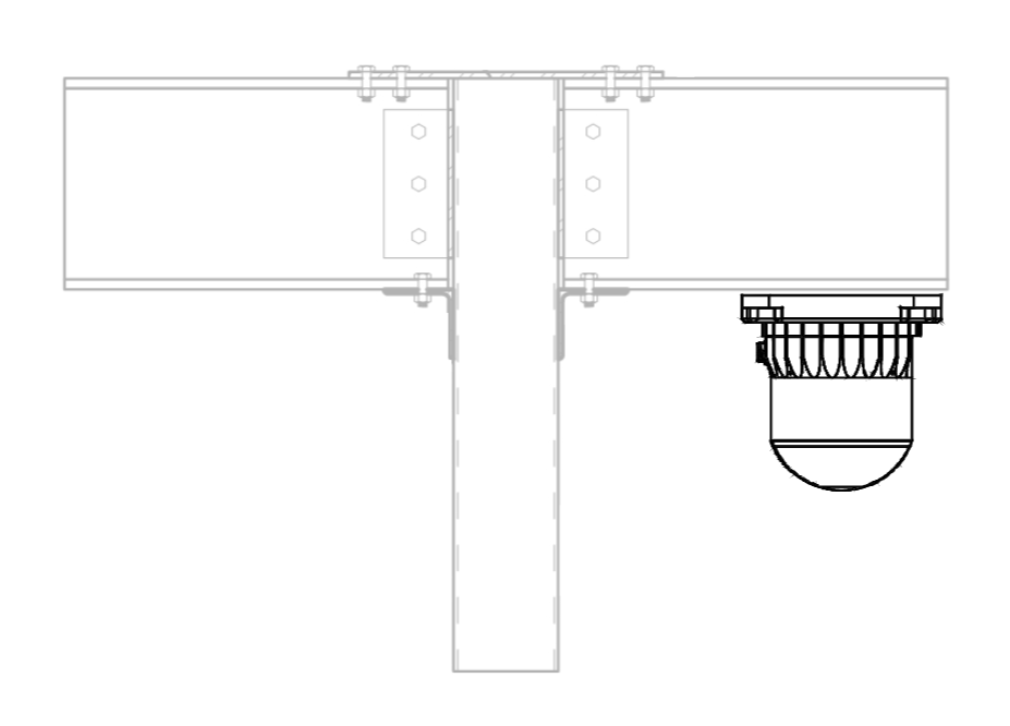
OSDome mounted on a shaft |
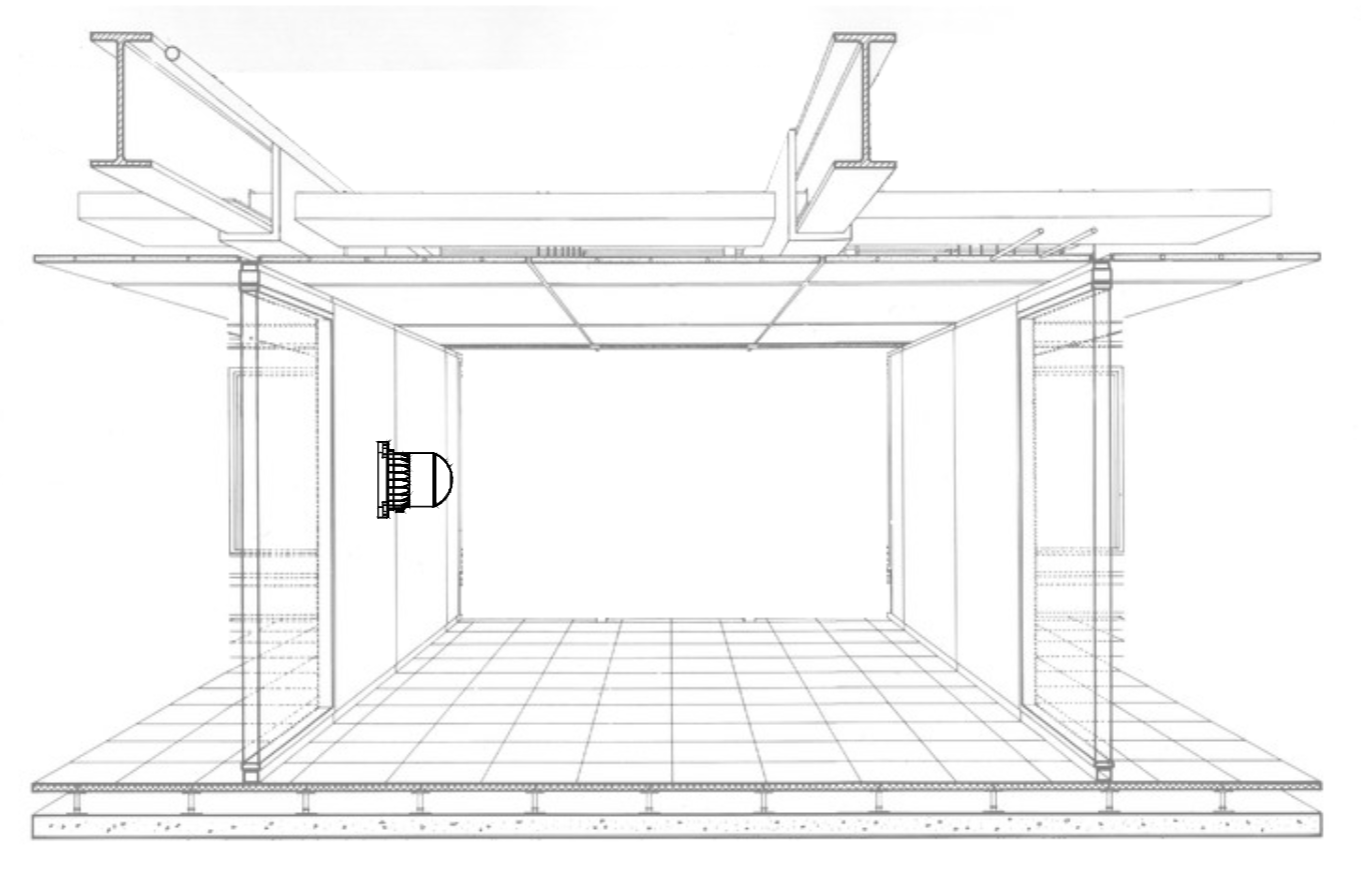
OSDome mounted on the side wall |
Mount to a material with high thermal conductivity. The following are recommended aluminum alloys and their thermal conductivities:
6061: 167 W/m-K
7075: 130 W/m-K
2024: 121 W/m-K
Ensure interfaces are clean and free from debris.
M3 screws are for mounting the sensor directly to the surface. M8 screws are used for mounting the base plate to the surface. The screw hole pattern is presented in the Sensor drawing above Sensor Components (Mechanical Drawings).
Torque bolts appropriately for the mount material and bolts. A torque of 120cNm is recommended for a2 stainless steel screws.
Use TIM (Thermal Interface Material) for any irregular or un-machined surfaces.
Use a thermally conductive pad to ensure good conductivity while not over constraining.
Ensure your implementation maintains the base of the sensor at no greater than 25ºC above ambient with an ambient less than 50ºC.
The shape of any heatsink should maximize the surface area for free and forced convection while being thick enough to allow the heat to conduct through the material.
Mounting on a drywall:
When mounting a sensor (needs to be mounted on a baseplate) on a drywall or a false ceiling, Ouster recommends the mounting means must be able to support 3X the weight of the sensor.
Check the wall condition and make sure its not aging. If your drywall is ageing or deteriorating, it’s likely to bow and bend with the added weight of the sensor, baseplate and cables connected to it. This could cause a potentially dangerous situation where the wall anchors could pull out and leave the sensor hanging or drop down.
CAD Files and mechanical drawings are provided by Ouster to verify proper sensor and base plate dimensions that can help measuring the surface for proper placement and mounting.
Check for studs using a stud finder. As these studs are hidden behind drywall, you’ll need to locate them (if available) with a stud finder. Lay the stud finder flat on the wall where you want to position your sensor and turn it on. Slowly move it across the wall from left to right until it beeps or lights up. Note the location with a pencil mark and continue along the wall until you find the next stud. Continue this process until you’ve found all the studs where you plan to install the sensor.
Drill pilot holes and mount the sensor carefully. Make sure you check for proper installation and that all screws are tightly fit.
Mounting on a concrete wall:
Check the wall conditions before drilling any pilot holes and make sure there are no cracks or molds or hollow bricks.
Using the CAD Files and mechanical drawings provided by Ouster, mark a template with a pencil on the wall where you want to mount the sensor (needs to be mounted on a baseplate).
Using appropriate drill bit, drill pilot holes accordingly and mount the sensor carefully.
For concrete walls, make sure to choose an appropriate stainless steel screw or a wedge anchor based on the type of wall.
Make sure you check for proper installation of the sensor and that all screws are tightly fit.
Note
If you do not feel comfortable following the steps above for mounting please contact Ouster Support so we can walk you through the steps thoroughly.
Warning
The sensor cables are not rated for running in any environmental air handling space, including source ducts or air returns that are commonly the spaces above false ceilings and are not in compliance with NFPA 70 (US NEC), 300.22(B) and (C).
Please refer to section Mounting Interface Box for more information on mounting the interface box.
Sensor Grounding Simplified
For additional knowledge on grounding, please refer to a simplified grounding diagram below for Rev7 OSDome sensor.
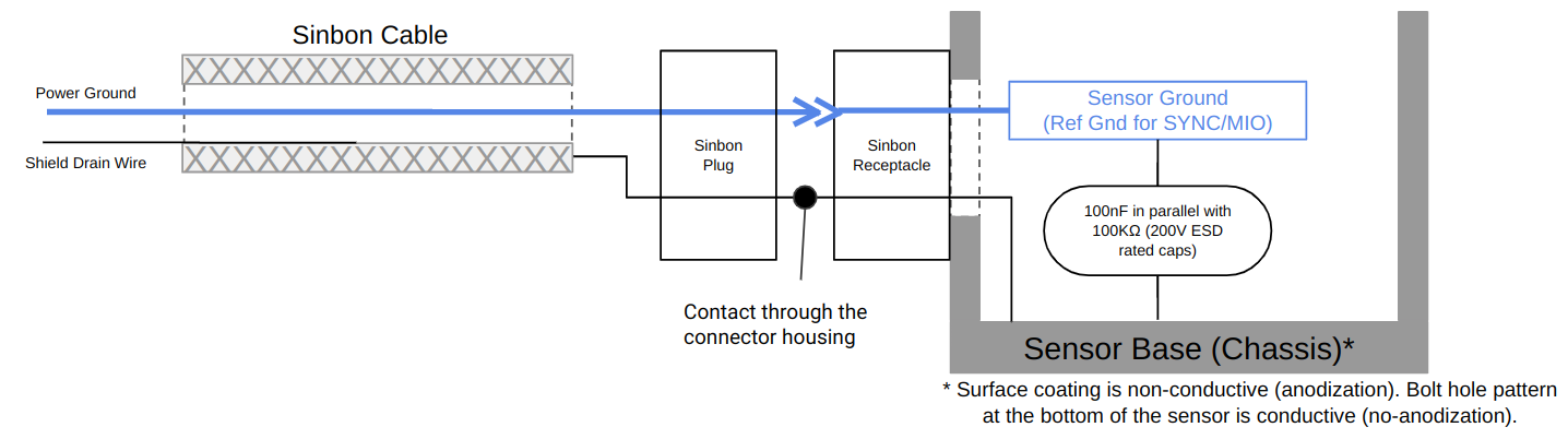
Grounding Diagram
Note
A black shielding drain wire is included for convenient bonding of the braided shield as required. It’s important to note that the drain wire is not connected to any pin in the sensor. The drain wire can be left unconnected unless the user wants to use it for EMI/EMC tests.
Operating Temperatures
Thermal requirements specific to Rev7 are listed below. The sensor has three operating states in order to manage high temperatures: Active, Shot Limiting, or Inactive. In the standard Active state the sensor will perform to the range and precision specifications of the datasheet. When the sensor reaches a certain temperature (see table below for reference), it enters Shot Limiting state and issues an alert.
In Shot Limiting state, the sensor reduces power to the lasers in order to reduce the thermal load. While in this state, sensor range and precision may degrade by up to 20%. When the sensor reaches the maximum operating temperature specified below, the sensor may become Inactive and shut off.
Convective Air Temp with Radial Heatsink and Standard Base |
|
Maximum temperature before shot limiting |
|
Temperature that shot limiting saturated (sensor may turn off above this temperature) |
|