Digital IO
SYNC_PULSE_IN
SYNC_PULSE_IN is a dedicated input channel that is accessible from the Interface Box. This channel expects an input pulse sequence which can be used for time synchronization. Refer to the Firmware User Manual for more information on configuring this input. Any references to pulse polarity in this document references the signal polarity on the SYNC_PULSE_IN pin of the sensor. This input channel is protected by an opto-isolator which will draw 5mA at full operation.
Parameter |
Min Voltage |
Max Voltage |
Min Driver Current |
|---|---|---|---|
LOGIC LOW |
-30 V |
2 V |
N/A |
LOGIC HIGH |
2.9 V |
30 V |
3mA @3.3V~5V, 5mA at 24V and higher |
SYNC_PULSE_IN Interface requirements were tested with 2 m cable Interface Box connection at 2 MHz.
When GPIO has 5 mA drive strength minimum, GPIO can be directly connected to the
SYNC_PULSE_INpin of the Interface Box header. This is the most common case and has been tested to work on common Arduino microcontroller series. Typical common logic levels of 3.3 V, 5 V GPIO of microcontrollers can produce drive strength of 5 mA min (Arduino, MSP430, etc.).If the 5 mA drive strength minimum cannot be met, a buffer circuit is required to drive
SYNC_PULSE_IN. Example circuits are provided for common 3.3 V and 5 V logic.
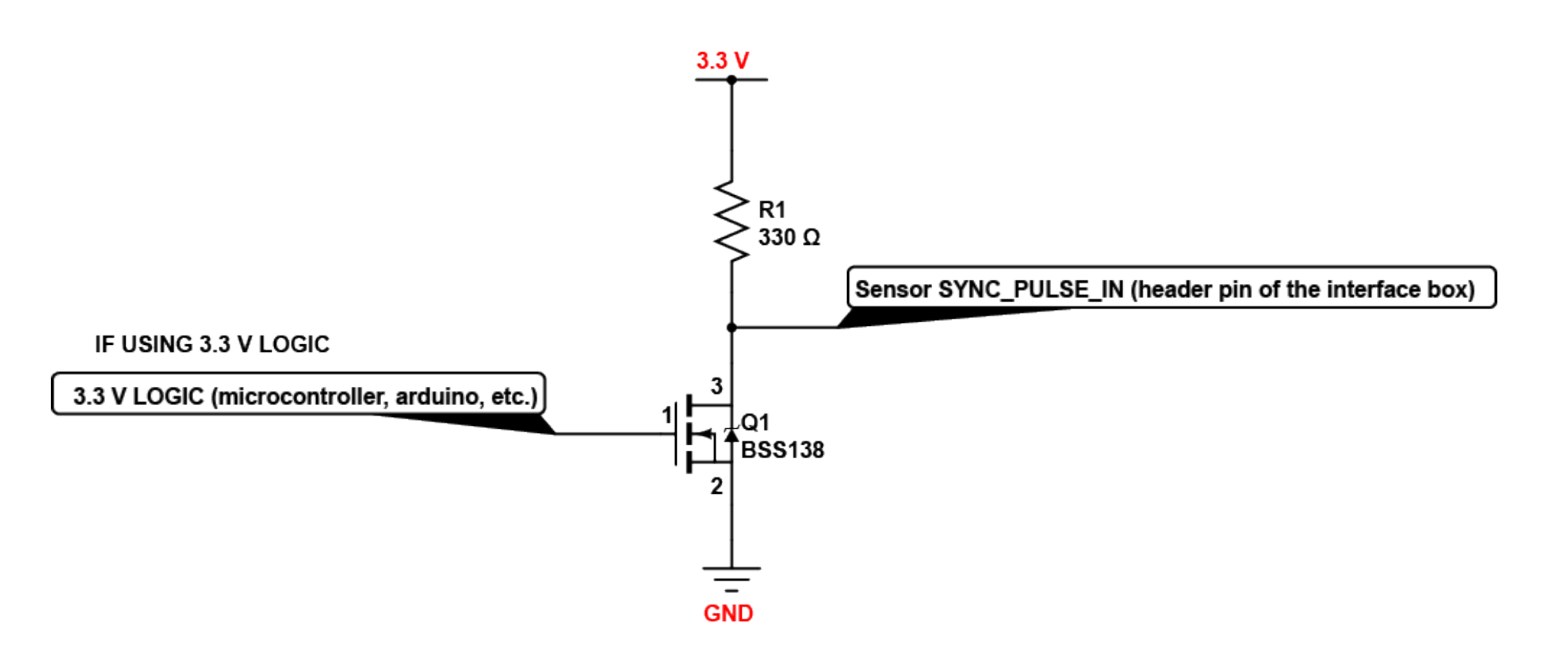
Example Circuit for 3.3 V
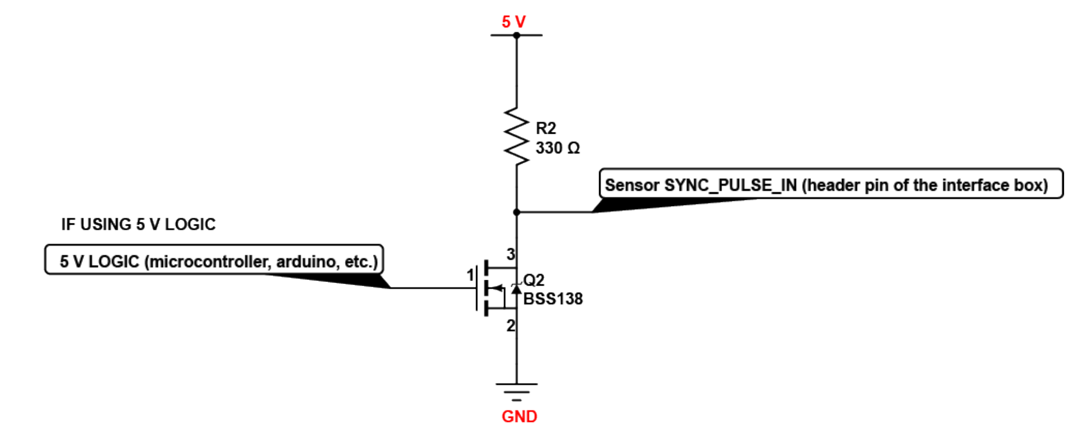
Example Circuit for 5 V logic
MULTIPURPOSE_IO (MIO)
MULTIPURPOSE_IO (MIO) is a configurable input or output channel accessible from the Interface Box. Detailed information on how to configure this channel using the sensor TCP interface can be found in the API guide. By default this channel is disabled.
When this channel is configured as an OUTPUT, the MIO sends a pulse sequence that can be used for time synchronization or event triggering outside the sensor. For a full description of output pulse triggering options, refer to the Firmware User Manual for more information. This output is an opto-isolated open collector circuit, relying on an externally provided pull-up resistor. This resistor is provided for a typical 3.3V/5V application as part of the Interface Box circuitry.
Parameter |
Min |
Max |
|---|---|---|
Pull Up Voltage |
3.3 V |
24 V |
Sinking Current |
N/A |
25 mA |
When this channel is configured as an INPUT, the MIO can accept a standard NMEA $GPRMC UART message. These messages are a common way for GPS systems to share timestamp information in UTC time format. More information on this packet structure and supported baud rates can be found in the Time Synchronization section of the Firmware User Manual.
Parameter |
Min Voltage |
Max Voltage |
Min Driver Current |
|---|---|---|---|
LOGIC LOW |
-30 V |
2 V |
N/A |
LOGIC HIGH |
2.9 V |
30 V |
3mA @3.3V~5V, 5mA at 24V and higher |
Above are tested with a 35m (200uH inductance) Interface Box at 115200 Baud.