Feature Guides
Cold Start
There is software-enabled capability for the Ouster sensor to power-up from lower temperatures. If the sensor detects that its environmental temperature is low, it will attempt to self-heat in a warmup state before entering a normal operating state.
Hardware Requirements
All Rev 7 sensors have cold startup capability.
Cold Start Operation
There is nothing for the user to change about the sensor configuration to use this feature. The sensor will automatically begin its warmup process in the coldest parts of its operating temperature range.
Product Line |
Min Temp Specs |
|---|---|
OS0 |
|
OS1 |
|
OS2 |
|
Indications and Alerts
In a cold start scenario, the sensor will have a short warmup phase; we’ve added in the additional "WARMUP" status to indicate when the sensor is warming up.
HTTP/1.1 200 OK
Connection: keep-alive
Content-Length: 274
Content-Type: application/json
Date: Thu, 01 Jan 1970 00:02:59 GMT
Server: nginx


{
    "build_date": "2023-1-15T15:56:07Z",
    "build_rev": "v3.0,0",
    "image_rev": "ousteros-image-prod-bootes-v3.0.0+0123456789",
    "initialization_id": 2573178,
    "prod_line": "OS-1-128",
    "prod_pn": "840-103xxx-0x",
    "prod_sn": "99xxxxxxxxxx",
    "status": "WARMUP"
}
The following alerts are related to cold start:
ID |
Category |
Level |
Description |
|---|---|---|---|
0x01000053 |
WARMUP_ISSUE |
ERROR |
Sensor warmup process has failed. Unit is shutting down. Check the sensor operating conditions are within operating bounds. Contact Ouster support with Diagnostic file. |
0x0100004F |
WARMUP_ISSUE |
WARNING |
Sensor warmup process is taking longer than expected; please ensure sensor is thermally constrained per requirements. Contact Ouster support with Diagnostic file. |
Sensor Telemetry
Sensor telemetry refers to sensor system state information that changes with time, i.e. temperature, voltage, etc. Users can monitor this data live or for diagnostics and take precautionary measures if needed. This information can be obtained from running the command GET /api/v1/sensor/telemetry as shown in the example below.
GET /api/v1/sensor/telemetry
To GET the sensor telemetry information.
http
GET /api/v1/sensor/telemetry HTTP/1.1
Host: 192.0.2.123
curl
curl -i -X GET http://192.0.2.123/api/v1/sensor/telemetry
httpie
http http://192.0.2.123/api/v1/sensor/telemetry
python-requests
requests.get('http://192.0.2.123/api/v1/sensor/telemetry')
response
HTTP/1.1 200 OK
Connection: keep-alive
Content-Length: 151
Content-Type: application/json
Date: Thu, 21 Mar 2024 05:26:49 GMT
Server: nginx

{
    "input_current_ma": 198,
    "input_voltage_mv": 24033,
    "internal_temperature_deg_c": 36,
    "phase_lock_status": "DISABLED",
    "timestamp_ns": 19510164553064
}
Fields |
Notes |
|---|---|
Timestamp |
Timestamp from the FPGA measured in |
Lidar Input Voltage |
Input voltage |
Lidar Input Current |
Input current |
Internal Temperature |
Internal base board temperature |
Phase Lock Status |
Different codes to specify phase lock status and issues related to phase locking ( |
Note
Phase lock output will not indicate loss of lock if the PTP source is lost.
Azimuth Window
Azimuth window selection is a feature to only turn on the UDP lidar data within a region of interest. The region of interest is defined by a min bound and a max bound, both in millidegrees. As a reminder, angles in this frame increment counterclockwise when viewed from the top. Below is the Lidar Coordinate Frame from a top-down perspective:
0° towards the external connectors
90° a quarter turn counterclockwise from the connector
180° opposite the connector
270° three quarter turns counterclockwise from the connector
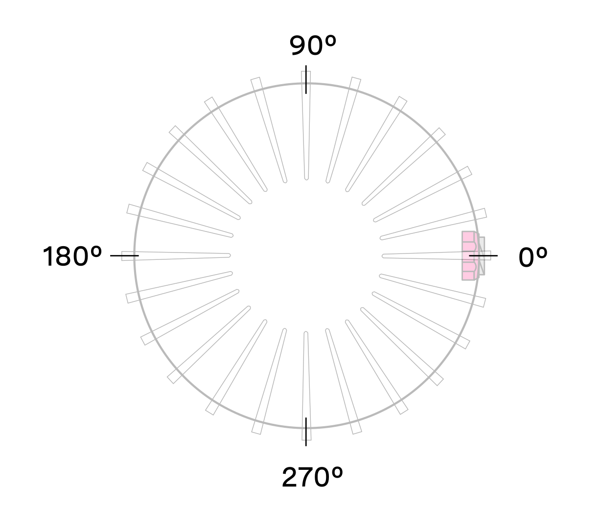
Lidar Coordinate Frame from a top-down perspective
Configuring the azimuth window lowers the average output data rate of the sensor. It also stops the lasers from firing during disabled regions and thus reduces power consumption and thermal output.
Expected Sensor Behavior
The sensor will round the input azimuth window bounds to the nearest Measurement Block IDs generating new ID-based bounds. The new bounds are used to mask Measurement Blocks in the lidar data packets. Lidar packets containing only masked Measurement Blocks are not output, and there may be partially masked Measurement Blocks in the two bookended lidar packets in each frame. The Measurement Block Status field will indicate the valid or masked/padded Measurement Blocks in any partially masked lidar packets. (See the Lidar Data Packet Format section for details on the lidar data format.)
The visualized output will contain jagged edges caused by the staggered, nonzero nature of the beam azimuth angles. It is necessary to set more conservative (wider) bounds to push the jagged edges beyond the desired window. This can be determined through trial and error or calculated deterministically with knowledge of the queryable beam azimuth angles.
Azimuth Laser Masking
This feature allows thermal improvement by shutting down the Lasers on the masked azimuth window. Lasers are only shot in the azimuth window the user has configured. When the user configures a limited azimuth window (azimuth_window config param) on the sensor for their application, the sensor will automatically shut down the lasers in the unused azimuth window.
Azimuth Window Examples
The HTTP API Guide lists the command for setting an azimuth window. Please refer to section azimuth_window.
The command syntax is as follows:
"azimuth_window": [min_bound_millidegrees, max_bound_millidegrees]
Default settings of 360° window: [0, 360000]
Set a region of interest between 0° to 180°: [0, 180000]
Set a region of interest between 270° to 90° with 180° field of view: [270000, 90000]
Set a region of interest 90° to 270° with 180° field of view: [90000, 270000]
Set a region of interest between 0° to 90° with 90° field of view: [0, 90000]
Set a region of interest 90° to 360° with 270° field of view: [90000, 0]
Standby Operating Mode
Starting with firmware v2.0.0, the sensor can be commanded in and out of a low-power Standby Operating Mode that can be useful for power, battery, or thermal-conscious applications of the sensor.
The HTTP config param operating_mode has a default value of NORMAL. Setting it to STANDBY puts the sensor into Standby Operating Mode upon reinitialization.
Expected Sensor Behavior
Power draw in Standby mode is 5W. The motor does not spin, and light is not visible from the window. However, the sensor is on and listening to commands. The sensor status will be STANDBY.
Standby Operating Mode Examples
Set sensor into
STANDBYmode and keep sensor inSTANDBYmode upon power-up at next use:
curl -i -X POST os-122322000614.local/api/v1/sensor/config -H 'content-type: application/json' --data-raw
'{"operating_mode": "STANDBY"}'
http
POST /api/v1/sensor/config HTTP/1.1
Host: 192.0.2.123
Content-Type: application/json

{"operating_mode": "STANDBY"}
curl
curl -i -X POST http://192.0.2.123/api/v1/sensor/config -H "Content-Type: application/json" --data-raw '{"operating_mode": "STANDBY"}'
httpie
echo '{
  "operating_mode": "STANDBY"
}' | http POST http://192.0.2.123/api/v1/sensor/config Content-Type:application/json
python-requests
requests.post('http://192.0.2.123/api/v1/sensor/config', headers={'Content-Type': 'application/json'}, json={'operating_mode': 'STANDBY'})
response
HTTP/1.1 204 No Content
Connection: keep-alive
Date: Thu, 01 Jan 1970 00:37:41 GMT
Server: nginx
Set sensor into
NORMALmode and keep sensor inNORMALmode upon power-up at next use:
curl -i -X POST os-122322000614.local/api/v1/sensor/config -H 'content-type: application/json' --data-raw
'{"operating_mode": "NORMAL"}'
http
POST /api/v1/sensor/config HTTP/1.1
Host: 192.0.2.123
Content-Type: application/json

{"operating_mode": "NORMAL"}
curl
curl -i -X POST http://192.0.2.123/api/v1/sensor/config -H "Content-Type: application/json" --data-raw '{"operating_mode": "NORMAL"}'
httpie
echo '{
  "operating_mode": "NORMAL"
}' | http POST http://192.0.2.123/api/v1/sensor/config Content-Type:application/json
python-requests
requests.post('http://192.0.2.123/api/v1/sensor/config', headers={'Content-Type': 'application/json'}, json={'operating_mode': 'NORMAL'})
response
HTTP/1.1 204 No Content
Connection: keep-alive
Date: Thu, 01 Jan 1970 00:37:41 GMT
Server: nginx
Signal Multiplier
The signal_multiplier config parameter allows the user to set a multiplier for the signal strength of the sensor. By default the sensor has a signal multiplier value of 1. Choosing a signal multiplier greater than 1 requires reducing the azimuth window below 360˚ as explained below. Lasers are disabled outside of the maximum allowable azimuth window.
Use Cases
The config parameter signal_multiplier <0.25/0.5/1/2/3> sets the signal multiplier value. The higher the signal multiplier value, the smaller the maximum azimuth window can be.
Signal Multiplier Value |
Max Azimuth Window |
|---|---|
0.25 |
360° |
0.5 |
360° |
1 ( Default) |
360° |
2 |
180° |
3 |
120° |
Besides affecting the sensor’s signal strength, the signal multiplier choice can also impact power draw and thermal behavior. Choosing a signal multiplier less than 1 reduces overall power. Similarly, choosing a smaller azimuth window means the lasers do not emit pulses in sections not included in the azimuth window, thus reducing overall power. However, while this can increase the max operating temp of the sensor, it can also degrade the performance at low temperatures. This discrepancy will be resolved in a future firmware. The table below outlines some example use cases. User can access Sensor Telemetry information and monitor the sensor temperature.
Use Case |
Parameter
|
Parameter
|
|---|---|---|
Signal boost |
3 |
[0,120000] |
Signal boost with power draw reduction |
2 |
[0,90000] |
Expected Behavior
For all signal multiplier levels, the lasers are enabled only in the chosen azimuth window.
If an invalid combination of signal multiplier and azimuth window values are set, the sensor will throw an error. If a valid pair of values are set, upon reinitializing, the sensor will operate in the signal multiplier mode.
Examples
The following shows the HTTP API example commands and responses.
Set sensor in 3x signal multiplier mode with 120° HFoV:
First set the azimuth_window to [120000, 240000] using azimuth_window. Then the user can run a POST command to set signal multiplier to a value 3.
curl -i -X POST 192.0.2.123/api/v1/sensor/config -H 'content-type: application/json' --data
'{"signal_multiplier": "3"}'
http
POST /api/v1/sensor/config HTTP/1.1
Host: 192.0.2.123
Accept: application/json

{"signal_multiplier": "3"}
curl
curl -i -X POST http://192.0.2.123/api/v1/sensor/config -H "Accept: application/json" --data-raw '{"signal_multiplier": "3"}'
httpie
echo '{"signal_multiplier": "3"}' | http POST http://192.0.2.123/api/v1/sensor/config Accept:application/json
python-requests
requests.post('http://192.0.2.123/api/v1/sensor/config', headers={'Accept': 'application/json'}, data='{"signal_multiplier": "3"}')
response
HTTP/1.1 204 No Content
Server: nginx
Date: Mon, 04 Mar 2024 19:50:36 GMT
Connection: keep-alive
Sensor will throw an error if invalid parameters set are of any value other than 0.25, 0.5, 1, 2, 3.
Note
Please refer to the Maximum azimuth window size at each signal multiplier level before configuring a signal multiplier value.
Sensor Performance by Operating Configuration
Depending upon the sensor’s lidar mode and signal multiplier setting, the sensor performance will vary from its baseline as listed on the datasheet. This section will present the estimated performance multiplier depending on the sensor and the operating configuration.
Estimated range multiplier
When using a signal multiplier higher than 1x and depending on the lidar mode, the sensor will get a range increase. The following tables present an estimated range multiplier depending on the operating configuration.
For the OS0, OSDome and OS1 sensors the baseline is the 1024x10 mode.
Signal Multiplier |
0.25x |
0.5x |
1x |
2x |
3x |
|---|---|---|---|---|---|
10 Hz |
0.84 |
1 |
1.19 |
1.41 |
1.57 |
20 Hz |
0.71 |
0.84 |
1 |
1.19 |
1.32 |
Signal Multiplier |
0.25x |
0.5x |
1x |
2x |
3x |
|---|---|---|---|---|---|
10 Hz |
0.71 |
0.84 |
1 |
1.19 |
1.32 |
20 Hz |
0.59 |
0.71 |
0.84 |
1 |
1.11 |
Signal Multiplier |
0.25x |
0.5x |
1x |
2x |
3x |
|---|---|---|---|---|---|
10 Hz |
0.59 |
0.71 |
0.84 |
1 |
1.11 |
20 Hz |
NA |
NA |
NA |
NA |
NA |
Note
The values in the tables above are given for guidance only. The only specs guaranteed are the ones defined in the datasheet for a specific mode.
For Rev7 OS2 sensors the baseline is the 2048x10 mode.
Frame Rate / Horiz. Res. |
512 |
1024 |
2048 |
||||||
|---|---|---|---|---|---|---|---|---|---|
Signal multiplier |
1x |
2x |
3x |
1x |
2x |
3x |
1x |
2x |
3x |
10 Hz |
1.41 |
1.68 |
1.86 |
1.19 |
1.41 |
1.57 |
1.00 |
1.19 |
1.32 |
20 Hz |
1.19 |
1.41 |
1.57 |
1.00 |
1.19 |
1.32 |
NA |
||
Note
The values in the tables above are given for guidance only. The only specs guaranteed are the ones defined in the datasheet for a specific mode.
Maximal representable range
Depending upon the signal multiplier, the maximal representable range of the sensor will be different. The table below shows the maximal representable range values for each sensor type and multiplier value.
Signal Multiplier |
OSDome (FW 3.x) |
OS0 (FW 3.x) |
OS1 (FW 3.x) |
|---|---|---|---|
0.25x, 0.5x, 1x |
233 m (Typical) 207 m (min) |
233 m (Typical) 207 m (min) |
233 m (Typical) 207 m (min) |
2x |
116 m (Typical) 103 m (min) |
116 m (Typical) 103 m (min) |
116 m (Typical) 103 m (min) |
3x |
77 m (Typical) 69 m (min) |
77 m (Typical) 69 m (min) |
77 m (Typical) 69 m (min) |
Signal Multiplier |
OS2 (FW 2.5.x) |
|---|---|
0.25x, 0.5x, 1x |
404 m (Typical) 381 m (min) |
2x |
202 m (Typical) 190 m (min) |
3x |
134 m (Typical) 127 m (min) |
Note
Range returns beyond the maximal representable range may experience range aliasing. Therefore, these modes are only recommended in scenarios where there will not be any returns beyond the maximal representable range.
Shot Limiting
Shot limiting is a process by which the Ouster sensor will automatically enter into state to safely prolong the operational performance of the sensor in high operating temperature conditions. There are several different levels of shot limiting that are described in the Shot Limiting Status Flags table.
The sensor has three operating states in order to manage high temperatures:
NORMAL (Status 0x00)
SHOT_LIMITING_IMMINENT (Status 0x01)
SHOT_LIMITING (Status 0x02 and greater)
In the NORMAL state the sensor will perform to the range and precision specifications of the datasheet. When the sensor reaches a certain temperature, the sensor enters the SHOT_LIMITING_IMMINENT state and issues alert 0x0100000E which indicates shot-limiting will commence in 30 seconds. After 30 seconds have elapsed and the temperature remains elevated, the sensor issues alert 0x0100000F and enters a SHOT_LIMITING state.
In shot limiting state, the sensor reduces power to the lasers in order to reduce the thermal load. While in this state, sensor range and precision may degrade by up to 30%. The sensor will progressively increase shot limiting if the temperature remains elevated. If the sensor reaches its maximum degree of shot-limiting, it will throw alert 0x0100003A.
If the sensor cools down while it is in either SHOT_LIMITING_IMMINENT or SHOT_LIMITING state, the sensor will return to the NORMAL state.
An independent state machine runs for thermal shutdown. When the sensor reaches the maximum operating temperature specified in the table Maximum Thermal Performance, the sensor will enter a SHUTDOWN_IMMINENT state and issue an alert in category OVERTEMP. If the sensor temperature remains elevated after 30 seconds, the sensor will shut down and issue alert 0x0100006B.
Note
Please refer to the Hardware User Manual to learn more about the maximum thermal performance.
Information regarding the shot limiting status is presented as part of the lidar data packet in the Configurable Data Packet Format. Shot limiting status will be a part of the packet header when config parameter udp_profile_lidar is set to one of the following values shown below.
The following flags are present in configurable data packet header:
Shot limiting status [4 bit unsigned int] - Indicates the shot limiting status of the sensor. Different codes indicates whether the sensor is in Normal Operation or in Shot limiting.
Shutdown Status [4 bit unsigned int] - Indicates whether thermal shutdown is imminent. This can be due to shot limiting being saturated, or due to any other over temperature conditions and depending upon the situation the appropriate alert is generated. When thermal shutdown is imminent, this flag will be set to 1 and the Thermal Shutdown Countdown field will be set to 30 seconds.
Shot limiting Countdown [8 bit unsigned int] - Countdown from 30 seconds to indicate when shot limiting is imminent. When the condition for entering shot limiting is met, the shot limiting status bit is set to 0x01 and the alert 0x0100000E takes effect. At this point the shot limiting counter will be set to 30 seconds and a countdown to initiate shot limiting will start.
Shutdown Countdown [8 bit unsigned int] - Countdown from 30 seconds to indicate that thermal shutdown is imminent. When a thermal shutdown is completed, the alert 0x0100006B will take effect and the sensor will automatically go to the ERROR state and stop outputting data.
The following table describes the codes in the shot limiting status flags, and what mode it corresponds to:
Shot Limiting status flags |
Description |
|---|---|
|
Normal Operation. When the sensor is not in shot limiting, the shot limiting status flag will be set to 0x00, and shot limiting countdown will be set to 0x00. |
|
When the condition for entering Shot limiting is met, we set the Shot Limiting Status bit 0x01 and the alert 0x0100000E is in effect, informing that shot limiting is imminent. |
|
In this mode, we reduce the % of nominal laser duty cycle by 0-10% from NORMAL OPERATION. There will be an approximate reduction in the sensor max range by 3%. |
|
In this mode, we reduce the % of nominal laser duty cycle by 10-20% from NORMAL OPERATION. There will be an approximate reduction in the sensor max range by 6%. |
|
In this mode, we reduce the % of nominal laser duty cycle by 20-30% from NORMAL OPERATION. There will be an approximate reduction in the sensor max range by 9%. |
Shot Limiting status flags |
Description |
|---|---|
|
In this mode, we reduce the % of nominal laser duty cycle by 30-40% from NORMAL OPERATION. There will be an approximate reduction in the sensor max range by 12%. |
|
In this mode, we reduce the % of nominal laser duty cycle by 40-50% from NORMAL OPERATION. There will be an approximate reduction in the sensor max range by 16%. For OS2 and OSDome sensors this mode is when shot limiting is saturated and alert 0x0100003A is in effect. There will be an approximate reduction in the sensor max range by 21%. |
|
In this mode, we reduce the % of nominal laser duty cycle by 50-60% from NORMAL OPERATION. There will be an approximate reduction in the sensor max range by 21%. |
|
In this mode, we reduce the % of nominal laser duty cycle by 60-70% from NORMAL OPERATION. There will be an approximate reduction in the sensor max range by 25%. |
|
In this mode, we reduce the % of nominal laser duty cycle by 70-75% from NORMAL OPERATION. There will be an approximate reduction in the sensor max range by 27%. For OS0 and OS1 sensors this mode is when shot limiting is saturated and alert 0x0100003A is in effect. There will be an approximate reduction in the sensor max range by 27%. |
Minimum Range Threshold
Minimum Range Threshold (cm) is a new feature added in FW v3.1 that reduces the minimum range of the sensor, enabling it to detect targets all the way up to the sensor window.
In the past, Ouster sensors were subject to a minimum range limitation dictated by the hardware revision. However, Ouster has made significant strides in overcoming this limitation. Now, users have the capability to eliminate the blind zone and extend the field of view (FOV) to the sensor window.
Additionally, users have the flexibility to configure the minimum range according to their specific requirements (Valid Values= 0cm, 30cm and 50cm).
Configuring min_range
Users can use HTTP API endpoint to set this parameter, please refer to min_range_threshold_cm.
Min_range_threshold=0 cm(Sensor Window): This setting allows the sensor to operate within its full range capability, from the closest detectable point up to the sensor window.Min_range_threshold=30 cm(Min_range of previous sensors i.e., Rev6 and prior): Users can set the minimum range to 30 cm, excluding detection within the first 30 cm from the sensor.Min_range_threshold=50 cm(Default for Rev7 and later): The default setting for Rev7 is a minimum range of 50 cm, providing a standard configuration for most applications.
Note
When min_range_threshold_cm is set to 30cm or less, Ouster recommends setting return_order to FARTHEST_TO_NEAREST, especially when the udp_profile_lidar is also set to Single Return. Also, for best performance in the region closer than 50cm, Ouster recommends keeping the sensor window clean.
Use Cases
Vehicle Applications: When mounted on vehicles or machinery, users have the flexibility to adjust the minimum range based on the detection of nearby objects. This feature helps in minimizing false positives and significantly enhances safety, as it ensures that the system responds accurately to potential obstacles or hazards in the vicinity.
Customized Sensing: In applications where specific ranges of interest are known in advance, such as robotics or drones, adjusting the minimum range allows for more precise and efficient sensing.
Environmental Adaptability: Users operating in challenging environments, such as crowded spaces or highly reflective surfaces, can tailor the sensor’s minimum range to improve performance and accuracy.
Filtering out unwanted detections: and focusing on relevant objects within the sensor’s field of view. This customization enhances data quality and reliability, particularly in complex operating environments.
Return Order
Overview
The Rev7 Ouster sensors are equipped with the capability to detect up to a total of 2 returns from the target. This hardware-enabled feature allows for the independent collection of information regardless of the lidar mode selected by the user, meaning the lidar can detect up to 2 returns in all modes including Single Return, Dual Return, and Low Data Rate modes.
With the introduction of Firmware 3.1, a new feature has been introduced, allowing users to sort returns by their order of detection. This feature enables users to rearrange returns based on factors such as range or signal strength, providing the ability to optimize sensor performance to meet specific application requirements.
Sorting Returns
Rev 7 sensors are capable of processing two returns, regardless of the udp_data_profile that has been selected (Single Return, Dual Return, Low Data Packet and FUSA Data Packet). Users can configure the sensor (using return_order) to order returns based on either signal strength or range. This flexibility allows for optimized data processing and interpretation, ensuring that the most relevant information is utilized for decision-making tasks.
This customization provides users with the ability to tailor the sensor’s behavior to suit their specific application requirements and this extends to the following data formats:
When return_order is selected the sensor returns the two strongest returns for each radial beam. The order in which these two returns appear depends on the setting of the return order which has the following possible values.
STRONGEST_TO_WEAKEST: The first return corresponds to the strongest signal strength among the two returns, while the subsequent return represents the next strongest signal (or the weaker of the two returns). This order of returns prioritizes points based on their signal strength, ensuring that the strongest signals are processed first. Such prioritization proves beneficial in applications where identifying the most prominent or reflective objects is essential.
FARTHEST_TO_NEAREST: The two returns are sorted based on their measured Range value. The first return corresponds to the farthest of the two returns, followed by the next strongest, and consequently the nearest of the two strongest returns. This order of returns arranges points according to their distance from the lidar sensor, listing the farthest points first. Such sorting proves invaluable when emphasis is placed on comprehending the spatial distribution of objects within the sensor’s field of view.
Note
When min_range_threshold_cm is set to 30cm or less, Ouster recommends setting return_order to FARTHEST_TO_NEAREST, especially when the udp_profile_lidar is also set to Single Return.
NEAREST_TO_FARTHEST: The nearest of the two strongest returns is the first return and the farthest of the two strongest returns follows. This return order prioritizes the closest point, listing it first. This order can be beneficial in applications where identifying nearby obstacles or points of interest is critical.
The choice of return order depends on the application. For example, in obstacle detection scenarios, NEAREST_TO_FARTHEST might be preferred for identifying nearby objects, whilst in mapping applications FARTHEST_TO_NEAREST could be more suitable for capturing the spatial layout of the environment.
The following return order can be set STRONGEST_TO_WEAKEST (Default), NEAREST_TO_FARTHEST and FARTHEST_TO_NEAREST. Users can use HTTP API endpoint to set this parameter, please refer to return_order. By default, the return_order parameter is set to STRONGEST_TO_WEAKEST. However, users can adjust this parameter according to their specific preferences.
User Editable Data Field
The User Editable Data Field is a versatile feature embedded within the Ouster Sensor, providing users with a preallocated text field for storing various types of information directly on the sensor itself. This field serves multiple purposes, including storing specific sensor information, calibration data, or any other relevant data crucial for operational efficiency.
Notably, the User Editable Data Field offers the flexibility to retain or delete its respective data, depending on the action taken, such as deleting the sensor configuration.
Note
Additional Information:
Valid values for UED: empty string or string containing non-binary ASCII and/or Unicode characters
Size limit for UED string: 128KB with 1KB = 1024bytes (Total = 131,072 bytes)
Example Use Case:
A common challenge faced by systems employing multiple Ouster sensors with differing hardware and firmware versions is ensuring the compatibility of mounted sensors with the application requirements. In scenarios where numerous sensors are deployed remotely and in large quantities, visually inspecting and identifying the appropriate sensor for each location becomes impractical. This lack of clarity can lead to incorrect installations and operational disruptions.
Proposed Solution:
To mitigate this challenge, a solution is proposed that harnesses the User Editable Field (UEF) on Ouster sensors, coupled with client-generated signatures using private keys. This solution aims to establish a robust validation mechanism, ensuring the authenticity and compatibility of Ouster lidar sensors within the users system.
Implementation of the Proposed Solution:
Ouster provides each sensor with a User Editable Field (UEF), initially empty, enabling users to write signatures without impacting core sensor functionality. This feature empowers users to customize and authenticate sensor data seamlessly.
Customer Signing Process:
Upon receiving a sensor, the customer retrieves the unique and unalterable serial number (SN) from the sensor.
The customer then employs their private key to sign the SN securely, generating a unique signature, which is subsequently written to the User Editable Field (UEF) on the sensor.
Customer System Validation:
During system startup, the customer’s system retrieves both the SN and the signature from the sensor.
Utilizing the customer’s widely available public key, the system meticulously verifies the signature within the UEF against the SN.
A successful verification assures the integrity of the sensor, confirming that it hasn’t been tampered with, and that the signature corresponds accurately to the intended sensor.
HTTP Endpoints for User Editable Field (UEF)
This field can be used for a number of purposes such as storing specific information about the sensor, qualifying a sensor, calibration data, or any other information.
Example HTTP API endpoints:
HTTP Endpoints for Optional Parameters - data policy
The policy key maps to the active policy as applied with PUT api/v1/user/data?policy=<policy_str>.
<policy_str> have the following options available:
clear_on_config_deleteby defaultkeep_on_config_delete
The User Editable Data comes with the ability to keep or delete its respective data based on the action of deleting the sensor config. That can be done by setting the value of the User Editable Data policy to either keep_on_config_delete or clear_on_config_delete (which is default), where if the keep_on_config_delete policy is set then the User Editable Data data will not be deleted when the sensor config is deleted, and if the clear_on_config_delete policy is set then the User Editable Data data will be deleted when the sensor config is deleted. The User Editable Data data and User Editable Data policy must be set in the same HTTP PUT request. If the User Editable Data value is set without the policy, then the policy will automatically be reset to clear_on_config_delete.
The User Editable Data data value (i.e. text) is persisted across sensor config resets, config reboots, firmware upgrades, and sensor power cycles.
When querying the User Editable Data, the include_metadata field can be specified to control the verbosity of the returned data. If set to ‘true’ then the value of the User Editable Data field will be returned in addition to the value of the policy. If set to ‘false’ (which is default) then only the value of the User Editable Data field will be returned.
Note
Data policy has no effect on the User Editable Data field.
Example HTTP API endpoints:
Optional Parameters - include_metadata
Same as nominal GET but returns a JSON dictionary of the form { "value": str, "policy": str } where the value key maps to the nominal value returned by GET with no arguments.
Note
include_metadata has no effect on the User Editable Data field.
This feature lets user to query the user editable data field to get policy and value when include_metadata is set to true/1 and only the value when include_matadata is set to false/0
Example HTTP API endpoints: