Multi-Sensor Synchronization
Phase Lock
Phase locking allows a sensor to consistently pass through a specific angle at the top, tenth (1024X10 Hz mode), or the twentieth (1024x20 Hz mode) of a second on each rotation. The phase lock control loop runs at 1000 Hz. Phase locking is useful for synchronizing a sensor with other devices including camera, radar, and other lidar.
A sensor must first be time-synchronized from an external source and must be in either the TIME_FROM_PTP_1588 or TIME_FROM_SYNC_PULSE_IN timestamp_mode before entering phase lock.
Phase Locking Reference Frame
Phase locking commands use angles defined in the Lidar Coordinate Frame in millidegrees. As a reminder, angles in this frame increment counterclockwise when viewed from the top. Below is the Lidar Coordinate Frame from a top-down perspective:
0° towards the external connector
90° a quarter turn counterclockwise from the connector
180° opposite the connector
270° three quarter turns counterclockwise from the connector
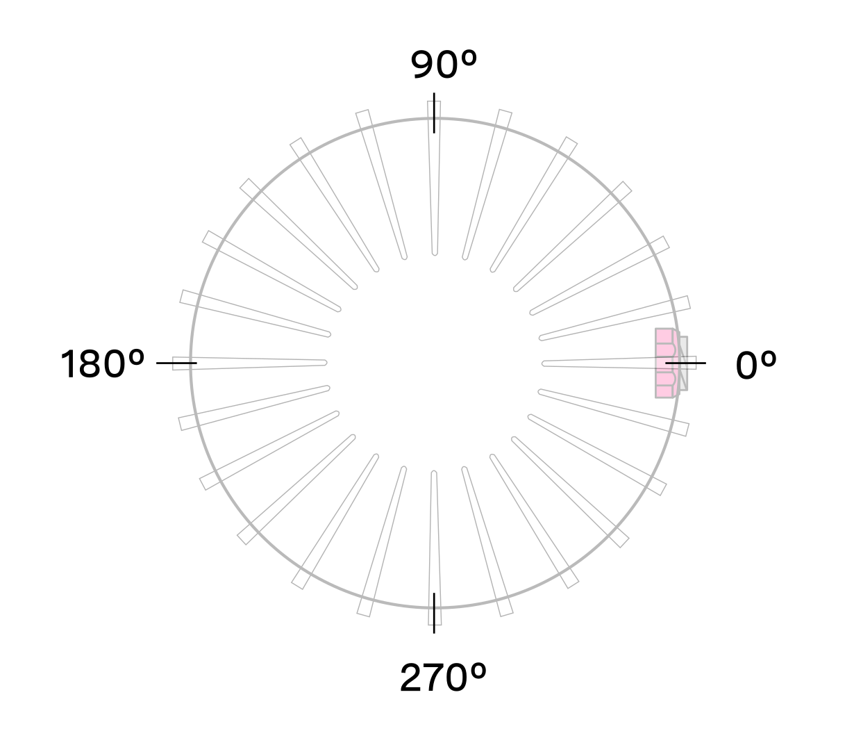
Lidar coordinate frame Top-Down view
Phase Locking Commands
Command to enable or disable phase lock:
By default, phase_lock_enable is false. Please use the below HTTP API Example.
http
POST /api/v1/sensor/config HTTP/1.1
Host: 192.0.2.123
Accept: application/json
Content-Type: application/json

"phase_lock_enable:=false"
curl
curl -i -X POST http://192.0.2.123/api/v1/sensor/config -H "Accept: application/json" -H "Content-Type: application/json" --data-raw '"phase_lock_enable:=false"'
httpie
echo '"phase_lock_enable:=false"' | http POST http://192.0.2.123/api/v1/sensor/config Accept:application/json Content-Type:application/json
python-requests
requests.post('http://192.0.2.123/api/v1/sensor/config', headers={'Accept': 'application/json', 'Content-Type': 'application/json'}, json='phase_lock_enable:=false')
response
HTTP/1.1 204 No Content
Connection: keep-alive
Date: Mon, 04 Mar 2024 21:20:16 GMT
Server: nginx
Command to set the phase lock offset angle in the Lidar Coordinate Frame:
By default, phase_lock_offset value is 0. <angle_in_millidegrees> is an integer from 0 to 360000. Please use the below HTTP API Example to set phase_lock_offset from 0 to 180000.
http
POST /api/v1/sensor/config HTTP/1.1
Host: 192.0.2.123
Accept: application/json
Content-Type: application/json

"phase_lock_offset:=180000"
curl
curl -i -X POST http://192.0.2.123/api/v1/sensor/config -H "Accept: application/json" -H "Content-Type: application/json" --data-raw '"phase_lock_offset:=180000"'
httpie
echo '"phase_lock_offset:=180000"' | http POST http://192.0.2.123/api/v1/sensor/config Accept:application/json Content-Type:application/json
python-requests
requests.post('http://192.0.2.123/api/v1/sensor/config', headers={'Accept': 'application/json', 'Content-Type': 'application/json'}, json='phase_lock_offset:=180000')
response
HTTP/1.1 204 No Content
Connection: keep-alive
Date: Mon, 04 Mar 2024 21:20:16 GMT
Server: nginx
Multi-sensor Example
In this example below, we are trying to phase lock all three sensors on the car so that they point towards the front of the car at the same time. Note that their external connectors point in different directions.
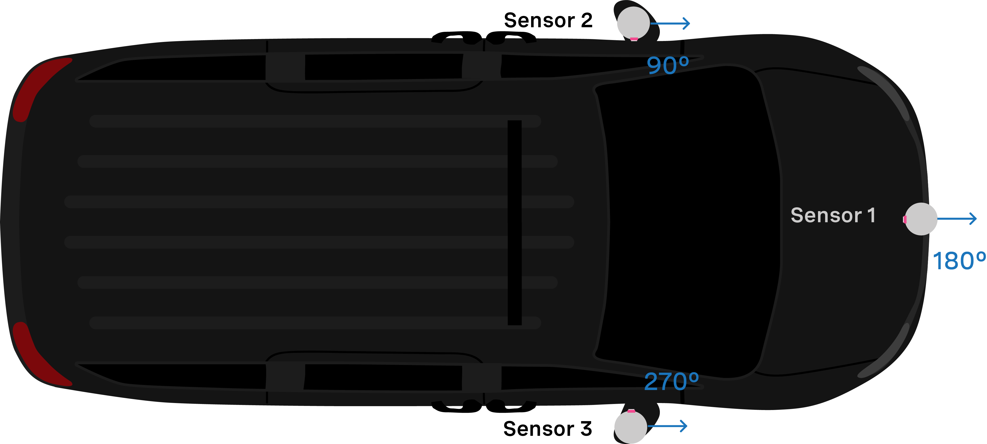
Van with 3 Sensors mounted
Assuming the three sensors are properly time synchronized via an external source, the following shows the netcat console input commands and responses from configuring the sensors so that they point forward at the same time.
Set Sensor 1 to phase lock at 180°:
http
POST /api/v1/sensor/config HTTP/1.1
Host: 192.0.2.123
Accept: application/json
Content-Type: application/json

"phase_lock_offset:=180000"
curl
curl -i -X POST http://192.0.2.123/api/v1/sensor/config -H "Accept: application/json" -H "Content-Type: application/json" --data-raw '"phase_lock_offset:=180000"'
httpie
echo '"phase_lock_offset:=180000"' | http POST http://192.0.2.123/api/v1/sensor/config Accept:application/json Content-Type:application/json
python-requests
requests.post('http://192.0.2.123/api/v1/sensor/config', headers={'Accept': 'application/json', 'Content-Type': 'application/json'}, json='phase_lock_offset:=180000')
response
HTTP/1.1 204 No Content
Connection: keep-alive
Date: Mon, 04 Mar 2024 21:20:16 GMT
Server: nginx
Set Sensor 2 to phase lock at 90°:
http
POST /api/v1/sensor/config HTTP/1.1
Host: 192.0.2.123
Accept: application/json
Content-Type: application/json

"phase_lock_offset:=90000"
curl
curl -i -X POST http://192.0.2.123/api/v1/sensor/config -H "Accept: application/json" -H "Content-Type: application/json" --data-raw '"phase_lock_offset:=90000"'
httpie
echo '"phase_lock_offset:=90000"' | http POST http://192.0.2.123/api/v1/sensor/config Accept:application/json Content-Type:application/json
python-requests
requests.post('http://192.0.2.123/api/v1/sensor/config', headers={'Accept': 'application/json', 'Content-Type': 'application/json'}, json='phase_lock_offset:=90000')
response
HTTP/1.1 204 No Content
Connection: keep-alive
Date: Mon, 04 Mar 2024 21:20:16 GMT
Server: nginx
Set Sensor 3 to phase lock at 270°:
http
POST /api/v1/sensor/config HTTP/1.1
Host: 192.0.2.123
Accept: application/json
Content-Type: application/json

"phase_lock_offset:=270000"
curl
curl -i -X POST http://192.0.2.123/api/v1/sensor/config -H "Accept: application/json" -H "Content-Type: application/json" --data-raw '"phase_lock_offset:=270000"'
httpie
echo '"phase_lock_offset:=270000"' | http POST http://192.0.2.123/api/v1/sensor/config Accept:application/json Content-Type:application/json
python-requests
requests.post('http://192.0.2.123/api/v1/sensor/config', headers={'Accept': 'application/json', 'Content-Type': 'application/json'}, json='phase_lock_offset:=270000')
response
HTTP/1.1 204 No Content
Connection: keep-alive
Date: Mon, 04 Mar 2024 21:20:16 GMT
Server: nginx
Accuracy
The following chart shows the expected angular position accuracy under normal operating conditions.
Product line |
10Hz |
20Hz |
|---|---|---|
OS0 and OS1 (Gen 1 and Gen 2) |
0.5˚ |
0.5˚ |
OS2 |
5˚ |
10˚ |
Phase Locking Alerts
The following alerts related to phase locking errors are listed below. For the full list of alerts and errors see the Alerts and Errors section in the Appendix.
id |
category |
level |
description |
|---|---|---|---|
0x01000050 |
MOTOR_CONTROL |
WARNING |
The phase lock offset error has exceeded the threshold. |
0x01000051 |
MOTOR_CONTROL |
ERROR |
The phase lock control failed to achieve a lock multiple times; please contact Ouster at https://ouster.com/tech-support. |
0x01000024 |
STARTUP |
ERROR |
The phase lock control failed to achieve a lock during startup. |
Note
For information on how to mitigate crosstalk between different Ouster lidars in the same system refer to Inter-sensor Interference Mitigation section of this manual.
Inter-sensor Interference Mitigation
Inter-sensor crosstalk occurs when two sensors are operating close together and they interpret each other’s laser pulses as their own. Mitigating crosstalk between two sensors is a two step process:
Phase lock the two sensors
Set azimuth window on each sensor so that they don’t send data when they are pointing at each other
Two Sensor Example
In this example below, we are trying to mitigate inter-sensor crosstalk between Sensor 1 and Sensor 2 on the car. Both of their connectors are facing towards the back of the car. The Lidar Coordinate Frame is printed on the back of the vehicle for reference.

Example: Inter-sensor crosstalk mitigation between 2 sensors
First and foremost, placing a physical barrier between the two sensors is the best option to mitigate cross talk in this example and most scenarios. If this is not possible, we can use the phase locking feature to eliminate the problem. Crosstalk only occurs when one sensor shines its lasers into the window of another sensor. The goal of phase locking is to force the sensors to point at each other simultaneously so that crosstalk occurs when sensors aren’t generating important data about the environment.
Time synchronize the two sensors via an external source. See the Time Synchronization section for more details on time synchronizing sensors with an external GPS or via PTP.
Phase lock both sensors such that they point directly at each other at the same time. In this case, we want Sensor 1 to be pointing at 90° at the same time that Sensor 2 is pointing at 270°. The example netcat console output would look like below.
Note
In the examples below, to distinguish between the command and expected response, a dash has been added before the expected response. The actual response will be without the dash.
Example: Set Sensor 1 to phase lock at 90°:
Step 1: Set “phase_lock_enable” to
true
http
POST /api/v1/sensor/config HTTP/1.1
Host: 192.0.2.123
Accept: application/json
Content-Type: application/json

"phase_lock_enable:=true"
curl
curl -i -X POST http://192.0.2.123/api/v1/sensor/config -H "Accept: application/json" -H "Content-Type: application/json" --data-raw '"phase_lock_enable:=true"'
httpie
echo '"phase_lock_enable:=true"' | http POST http://192.0.2.123/api/v1/sensor/config Accept:application/json Content-Type:application/json
python-requests
requests.post('http://192.0.2.123/api/v1/sensor/config', headers={'Accept': 'application/json', 'Content-Type': 'application/json'}, json='phase_lock_enable:=true')
response
HTTP/1.1 204 No Content
Connection: keep-alive
Date: Mon, 04 Mar 2024 21:20:16 GMT
Server: nginx
Step 2: Set “phase_lock_offset” to
90000
http
POST /api/v1/sensor/config HTTP/1.1
Host: 192.0.2.123
Accept: application/json
Content-Type: application/json

"phase_lock_offset:=90000"
curl
curl -i -X POST http://192.0.2.123/api/v1/sensor/config -H "Accept: application/json" -H "Content-Type: application/json" --data-raw '"phase_lock_offset:=90000"'
httpie
echo '"phase_lock_offset:=90000"' | http POST http://192.0.2.123/api/v1/sensor/config Accept:application/json Content-Type:application/json
python-requests
requests.post('http://192.0.2.123/api/v1/sensor/config', headers={'Accept': 'application/json', 'Content-Type': 'application/json'}, json='phase_lock_offset:=90000')
response
HTTP/1.1 204 No Content
Connection: keep-alive
Date: Mon, 04 Mar 2024 21:20:16 GMT
Server: nginx
Example: Set Sensor 2 to phase lock at 270°:
Step 1: Set “phase_lock_enable” to
true
http
POST /api/v1/sensor/config HTTP/1.1
Host: 192.0.2.123
Accept: application/json
Content-Type: application/json

"phase_lock_enable:=true"
curl
curl -i -X POST http://192.0.2.123/api/v1/sensor/config -H "Accept: application/json" -H "Content-Type: application/json" --data-raw '"phase_lock_enable:=true"'
httpie
echo '"phase_lock_enable:=true"' | http POST http://192.0.2.123/api/v1/sensor/config Accept:application/json Content-Type:application/json
python-requests
requests.post('http://192.0.2.123/api/v1/sensor/config', headers={'Accept': 'application/json', 'Content-Type': 'application/json'}, json='phase_lock_enable:=true')
response
HTTP/1.1 204 No Content
Connection: keep-alive
Date: Mon, 04 Mar 2024 21:20:16 GMT
Server: nginx
Step 2: Set “phase_lock_offset” to
270000
http
POST /api/v1/sensor/config HTTP/1.1
Host: 192.0.2.123
Accept: application/json
Content-Type: application/json

"phase_lock_offset:=270000"
curl
curl -i -X POST http://192.0.2.123/api/v1/sensor/config -H "Accept: application/json" -H "Content-Type: application/json" --data-raw '"phase_lock_offset:=270000"'
httpie
echo '"phase_lock_offset:=270000"' | http POST http://192.0.2.123/api/v1/sensor/config Accept:application/json Content-Type:application/json
python-requests
requests.post('http://192.0.2.123/api/v1/sensor/config', headers={'Accept': 'application/json', 'Content-Type': 'application/json'}, json='phase_lock_offset:=270000')
response
HTTP/1.1 204 No Content
Connection: keep-alive
Date: Mon, 04 Mar 2024 21:20:16 GMT
Server: nginx
Set an azimuth window for both sensors. In this case, the region of interest for Sensor 1 is
 and the region of interest for Sensor 2 is
The calculation for and is as follows:
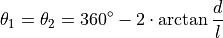
In this case, if the two sensors were placed a distance of 100 mm apart,  We want to set azimuth window of size 282° for the two sensors, so that they do not send data in the 78° where they would point at each other. Sensor 1’s azimuth window is the 282° centered around 270°. Sensor 2’s region of interest is the 282° centered around 90°.
Sensor 1’s azimuth window starts at 129° and follows the CCW direction to end at 51°:
Example CURL command:
curl -i -X POST 192.0.2.123/api/v1/sensor/config -H 'content-type: application/json' --data '{"azimuth_window": [129000, 51000]}'
Example HTTP command:
http POST 10.34.24.132/api/v1/sensor/config "azimuth_window:=[129000, 51000]"
http
POST /api/v1/sensor/config HTTP/1.1
Host: 192.0.2.123
Accept: application/json

"azimuth_window": [129000, 51000]
curl
curl -i -X POST http://192.0.2.123/api/v1/sensor/config -H "Accept: application/json" --data-raw '"azimuth_window": [129000, 51000]'
httpie
echo '"azimuth_window": [129000, 51000]' | http POST http://192.0.2.123/api/v1/sensor/config Accept:application/json
python-requests
requests.post('http://192.0.2.123/api/v1/sensor/config', headers={'Accept': 'application/json'}, data='"azimuth_window": [129000, 51000]')
response
HTTP/1.1 204 No Content
Server: nginx
Date: Thu, 28 Apr 2022 18:09:49 GMT
Connection: keep-alive
Sensor 2’s azimuth window starts at 309° and follows the CCW direction to end at 231°:
Example CURL command:
curl -i -X POST 192.0.2.123/api/v1/sensor/config -H 'content-type: application/json' --data '{"azimuth_window": [309000, 231000]}'
Example HTTP command:
http POST 10.34.24.132/api/v1/sensor/config "azimuth_window:=[309000, 231000]"
http
POST /api/v1/sensor/config HTTP/1.1
Host: 192.0.2.123
Accept: application/json

"azimuth_window": [309000, 231000]
curl
curl -i -X POST http://192.0.2.123/api/v1/sensor/config -H "Accept: application/json" --data-raw '"azimuth_window": [309000, 231000]'
httpie
echo '"azimuth_window": [309000, 231000]' | http POST http://192.0.2.123/api/v1/sensor/config Accept:application/json
python-requests
requests.post('http://192.0.2.123/api/v1/sensor/config', headers={'Accept': 'application/json'}, data='"azimuth_window": [309000, 231000]')
response
HTTP/1.1 204 No Content
Server: nginx
Date: Thu, 28 Apr 2022 18:09:49 GMT
Connection: keep-alive
Product Line |
At Window |
At base including fins |
|---|---|---|
OS0 and OS1 (Gen1 and Gen2) |
81mm |
88mm |
OS2 |
111mm |
121mm |
Time Synchronization
Timing Overview Diagram

Signal path with MULTIPURPOSE_IO set as input

Signal path with MULTIPURPOSE_IO set as output
Sensor Time Source
All lidar and IMU data is timestamped to a common timer with 10 nanosecond precision.
The common timer can be programmed to run off one of three clock sources:
An internal clock derived from a high accuracy, low drift oscillator.
An opto-isolated digital input from the external connector for timing off an external hardware trigger such as a GPS. The polarity of this input signal is programmable. For instance, both a GPS PPS pulse and a 30 Hz frame sync from an industrial camera can supply a timing signal to the sensor.
The IEEE 1588 Precision Time Protocol. PTP provides the convenience of configuring timing over a network that supports IEEE 1588 with no additional hardware signals.
Setting Ouster Sensor Time Source
The source for measurement timestamps can be configured using the timestamp_mode. The available modes are described below:
Command |
Response |
|---|---|
|
Use the internal clock. Free running counter based on the sensor’s internal oscillator. Counts seconds and nanoseconds since sensor turn on, reported at ns resolution (both a second and nanosecond register in every UDP packet), but minimum increment is on the order of 10 ns. |
|
A free running counter synced to the SYNC_PULSE_IN input counts seconds (# of pulses) and nanoseconds since sensor turn on. If |
|
Synchronize with an external PTP master. A monotonically increasing counter that will begin counting seconds and nanoseconds since startup. As soon as a 1588 sync event happens, the time will be updated to seconds and nanoseconds since 1970. The counter must always count forward in time. If another 1588 sync event happens the counter will either jump forward to match the new time, or slow itself down. It is reported at ns resolution (there is both a second and nanosecond register in every UDP packet), but the minimum increment varies. |
If configuring the sensor to synchronize time from an external sync pulse, the pulse polarity can be specified as described in the Sensor Configuration. Pulse-in frequency is assumed to be 1 Hz. For example, using POST commands will set the sensor to expect an active low pulse and configure the seconds timestamp to be pulse count since sensor startup:
Note
Please refer to HTTP API Reference Guide for detailed POST command.
To configure the multipurpose-io port of the sensor to accept an external NMEA UART message, the multipurpose_io_mode parameter must be set to INPUT_NMEA_UART as described in External Trigger Clock Source. Once a valid UART message is received by the sensor, the seconds timestamp will snap to the latest timestamp received. The expected NMEA UART message is configurable. For example, the below commands will set the sensor to accept an NMEA UART message that is active high with a baud rate of 115200 bits per second, add 27 additional leap seconds, and accept messages even with a valid character not set:
Note
After POST api/v1/sensor/config request is received successfully, the sensor will reinitialize automatically to make the new configuration active and the config settings are persisted across power cycles.
External Trigger Clock Source
Additionally, the sensor can be configured to output a SYNC_PULSE_OUT signal from a variety of sources. See example commands in the HTTP API Reference Guide section. Pulses will always be evenly spaced.
This can be enabled through the multipurpose_io_mode configuration parameter.
Configuration |
Response |
|---|---|
|
Do not output a |
|
Reconfigures the |
|
Output a |
|
Output a |
|
Output a |
|
Output a |
When the sensor’s multipurpose_io_mode is set to OUTPUT_FROM_INTERNAL_OSC, OUTPUT_FROM_SYNC_PULSE_IN, or OUTPUT_FROM_PTP_1588, then sync_pulse_out_frequency (Hz) parameter can be used to define the output rate. It defaults to 1 Hz. It should be greater than 0 Hz and maximum sync_pulse_out_frequency is limited by the criterion below.
When the sensor is set to OUTPUT_FROM_ENCODER_ANGLE, then the sync_pulse_out_angle (deg) parameter can be used to define the output pulse rate. This allows the user to output a SYNC_PULSE_OUT signal when the encoder passes a specified angle, or multiple of the angle, indexed from 0 crossing, in degrees. It should be an integer between 0 and 360 degrees, inclusive. However, the minimum sync_pulse_out_angle is also limited by the criterion below.
In all modes, the output pulse width is defined by sync_pulse_out_pulse_width (ms).
Note
If sync_pulse_out_pulse_width x sync_pulse_out_frequency is close to 1 second, the output pulses will not function (will not return to 0). For example, at 10 Hz rotation and a 10 ms pulse width, the limitation on the number of pulses per rotation is 9.
Examples
Here are examples and their effect on output pulse when lidar_mode is 1024x10, and assuming sync_pulse_out_pulse_width is 10 ms. Please refer to POST command examples on HTTP API Reference Guide for detailed command line.
Configuration (POST /api/v1/sensor/config) |
Response |
|---|---|
|
The output pulse frequency is 1 Hz. Each pulse is 10 ms wide. |
|
The output pulse frequency is 50 Hz. Each pulse is 10 ms wide. |
|
The output pulse frequency is 10 Hz, since the sensor is in 10 Hz mode (10 rotations / sec) and the angle is set to 360º, a full rotation. Each pulse is 10 ms wide. |
|
The output pulse frequency is 80 Hz, since the sensor is in 10 Hz mode (10 rotations / sec) and the angle is set to 45º. Each full rotation will have 8 pulses. Each pulse is 10 ms wide. |
NMEA Message Format
The Ouster Sensor expects a standard NMEA $GPRMC UART message. Data (called a sentence) is a simple ASCII string starting with a ‘$’ character and ending with a return character. Fields of the sentence are separated with a ‘,’ character, and the last field (a checksum) is separated by a ‘*’ character.
The max character length of a standard message is 80 characters; however, the Ouster Sensor can support non-standard messages up to 85 characters (see Example 2 below).
The Ouster Sensor will deliver time in the UDP packet by calculating seconds since 00:00:00 Thursday, 1 January 1970. nmea_leap_seconds by default is 0, meaning this calculation will not take into account any leap seconds. If nmea_leap_seconds is 0 then the reported time is Unix Epoch time. As of February, 2019, Coordinated Universal Time (UTC) lags behind International Atomic Time (TAI) by an offset of 37 seconds (10 seconds from the initial UTC offset when UTC was introduced in 1972 + 27 leap seconds announced in the intervening years). Therefore, setting nmea_leap_seconds to 37 in February of 2019 would make the timestamps match the TAI standard.
nmea_in_polarity by default is ACTIVE_HIGH. This means that a UART start bit will occur directly after a falling edge. If using RS-232, the UART signal may be inverted (where a start bit occurs directly after a rising edge). In this case, nmea_in_polarity should be set to ACTIVE_LOW.
Example 1 Message:
$GPRMC,123519,A,4807.038,N,01131.000,E,022.4,084.4,230394,003.1,W*6A
Field
Description
$GPRMC
Recommended Minimum sentence C
123519
Fix taken at 12:35:19 UTC
A
Status A=active or V=Void
4807.038
Latitude 48 deg 07.038’
N
Latitude cardinal reference
01131.000
Longitude 11 deg 31.000’
E
Longitude cardinal reference
022.4
Speed over the ground in knots
084.4
Track angle in degrees True
230394
Date - 23rd of March 1994
003.1
Magnetic Variation
W
Magnetic cardinal reference
A
[Optional] A=autonomous, D=differential, E=Estimated, N=not valid, S=Simulator
*6A
The checksum data, always begins with *
Example 2 Message:
$GPRMC,042901.00,A,3745.871698,N,12224.825960,W,0.874,327.72,130219,13.39,E,A,*60
Field
Description
$GPRMC
Recommended Minimum sentence C
042901.00
Fix taken at 4:29:01 UTC
A
Status A=active or V=Void
3745.871698
Latitude 37 deg 45.871698’
N
Latitude cardinal reference
12224.825960
Longitude 12 deg 24.825960’
W
Longitude cardinal reference
0.874
Speed over the ground in knots
327.72
Track angle in degrees True
130219
Date - 13th of February 2019
13.39
Magnetic Variation
E
Magnetic cardinal reference
A
[Optional] A=autonomous, D=differential, E=Estimated, N=not valid, S=Simulator
*60
The checksum data, always begins with *