Electrical Interface
Power Supply and Operating Voltage
The Ouster sensors are designed to operate with an input voltage range of 9.5V to 51V, making them suitable for 12VDC to 24VDC nominal systems, but not suitable for 48V nominal battery-based systems.
If the voltage at the sensor connector drops below 9.5V, a low voltage warning is triggered, and an under-voltage error occurs at 9.0V, at which point the sensor may shut down.
Over-voltage conditions and alarms occur at 51VDC, with an over-voltage lockout initiating at 58VDC (±1V) and releasing at 55VDC (±1V).
When using the sensor without the provided interface box, ensure that the power supply adheres to the specified operating voltage range and provides at least 20W of power.
Note
If operating at cold conditions the peak power consumption is between 22 W and 28 W. Peak power consumption is 28 W if operated at -40ºC for Rev7 OS-Dome, OS-0 and OS-1 (-20ºC for OS-2). Ouster recommends use of power no less than 30W if using in outdoor conditions. Please contact our Field Application Team can answer your questions and provide guidance for achieving proper operations.
Connection through the Interface Box
The Interface Box that accompanies the sensor is designed to allow the sensor to be operated for test and evaluation purposes in indoor environments only. It can be connected to the sensor with a cable equipped with connectors. It allows the sensor to be powered up and provides access to the sensor gigabit Ethernet Interface via a standard RJ45 connector. DC Power to the sensor is provided to the Interface Box by the accompanying 24V DC power supply.
Direct Cable Connection and Pinout
The Ouster sensor can be operated without the use of an Interface Box. In this case, a “pigtail” cable should be used by the user following the Pinout presented below. When used with direct cable connection, the sensor should still be operated within the operating voltage specified in section Power Supply and Operating Voltage.
Cable Pinout Diagram for Type 1, 2 and 3 (1000BASE-T)

Type 1, 2, 3 (1000BASE-T) |
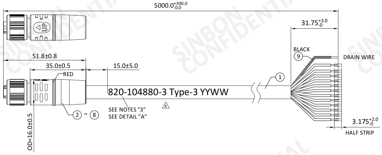
Type 3 Zinc and Stainless Steel CAD Drawing |
Note
A black shielding drain wire is included for convenient bonding of the braided shield as required. It’s important to note that the drain wire is not connected to any pin in the sensor. The drain wire can be left unconnected unless the user wants to use it for EMI/EMC tests.
Function |
Pin No. |
Wire Color |
Type-1, 24V |
Type-2, 24V |
Type-3, 12V |
Twisted with |
Color (Display) |
|---|---|---|---|---|---|---|---|
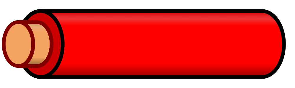
VCC |
1 |
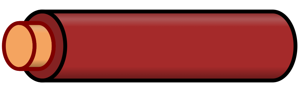
Red |
22 AWG |
22 AWG |
18 AWG |
N/A |
|
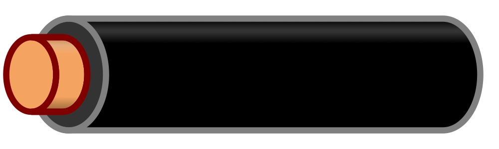
GROUND |
7 |
Black |
22 AWG |
22 AWG |
18 AWG |
N/A |
|
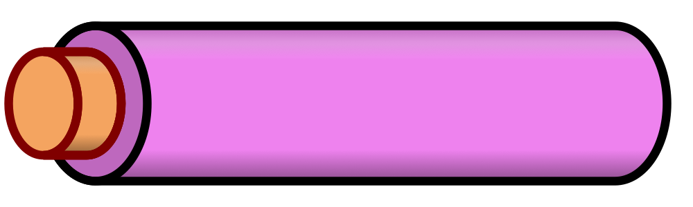
MULTI- PURPOSE_IO |
3 |
Purple |
26 AWG |
28 AWG |
28 AWG |
N/A |
|
SYNC _PULSE_IN |
2 |
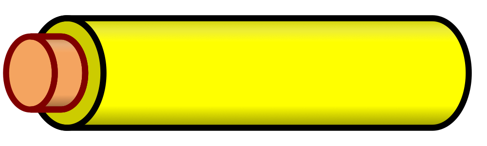
Yellow |
26 AWG |
28 AWG |
28 AWG |
N/A |
|
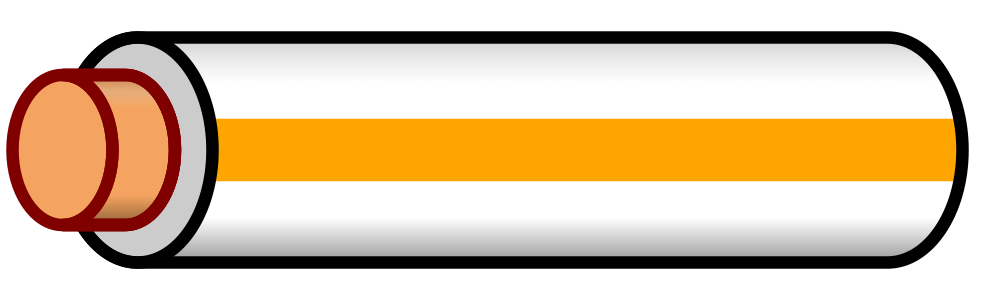
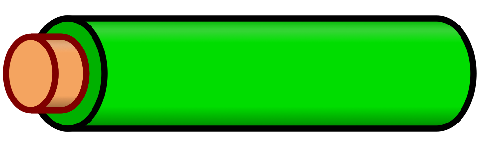
Ethernet BI_DA+ |
5 |
White /Orange |
26 AWG |
28 AWG |
28 AWG |
Orange |
|
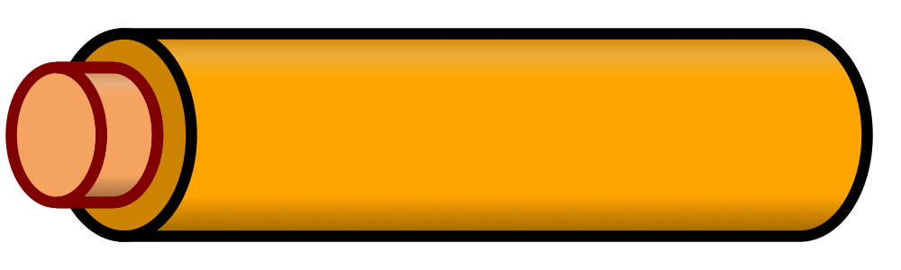
Ethernet BI_DA- |
4 |
Orange |
26 AWG |
28 AWG |
28 AWG |
White /Orange |
|
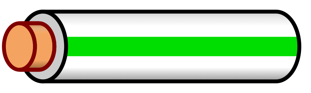
Ethernet BI_DB+ |
8 |
White /Green |
26 AWG |
28 AWG |
28 AWG |
Green |
|
Ethernet BI_DB- |
6 |
Green |
26 AWG |
28 AWG |
28 AWG |
White /Green |
|
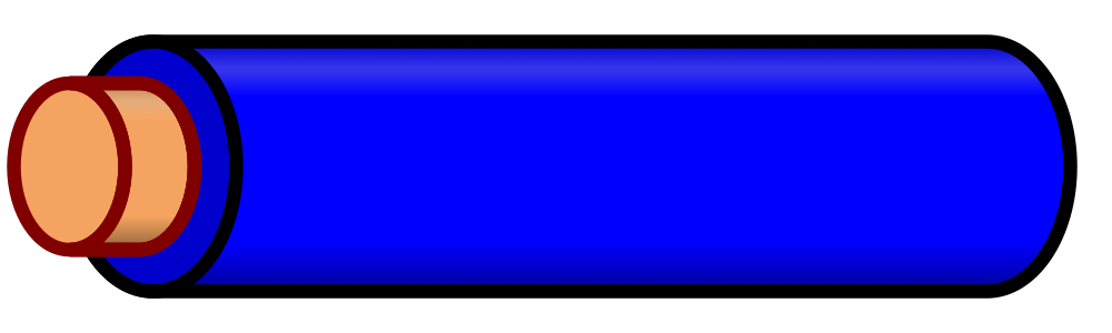
Ethernet BI_DC+ |
9 |
Blue |
26 AWG |
28 AWG |
28 AWG |
White /Blue |
|
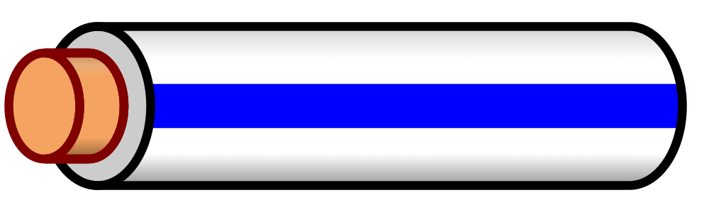
Ethernet BI_DC- |
10 |
White /Blue |
26 AWG |
28 AWG |
28 AWG |
Blue |
|
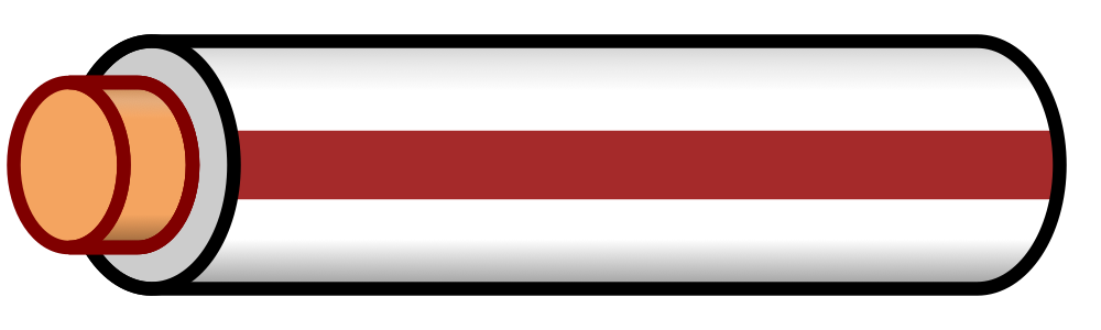
Ethernet BI_DD+ |
12 |
White /Brown |
26 AWG |
28 AWG |
28 AWG |
Brown |
|
Ethernet BI_DD- |
11 |
Brown |
26 AWG |
28 AWG |
28 AWG |
White /Brown |
|
Note
Cable pinout for Type 3 cables are the same for both Zinc and Stainless Steel connectors. Type 1 and Type 2 cable specifications are for reference only are NO longer available for purchase.
Cable Pinout Diagram for Type 4 (1000BASE-T1)
Note
Type 4 (1000BASE-T1) is only applicable for Rev7 (OS0, OS1 and OSDome) Sensors, please use this section only for reference as this is not available for Rev7 OS2 sensor.
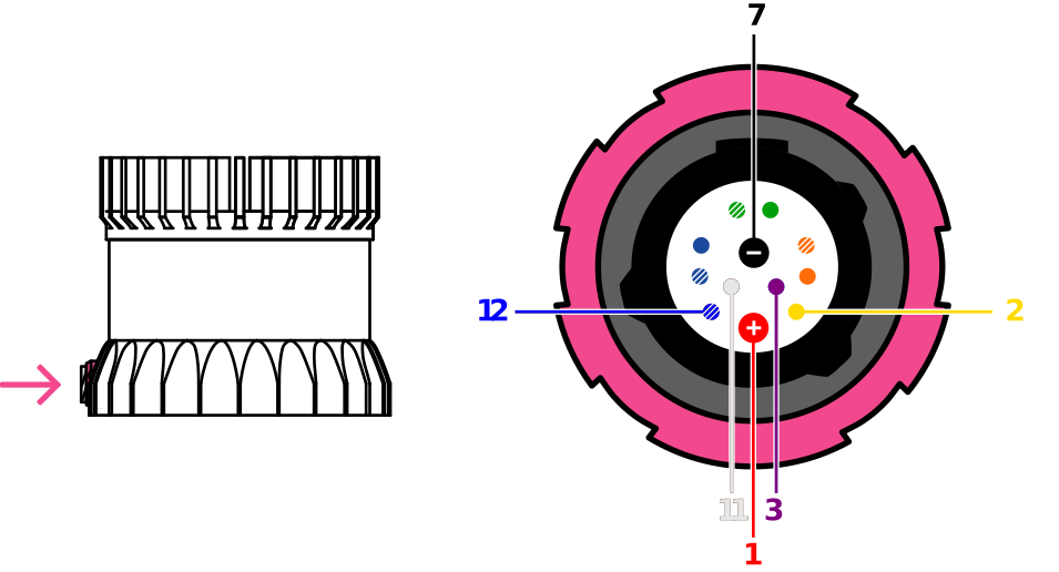
Type 4 (1000BASE-T1) |
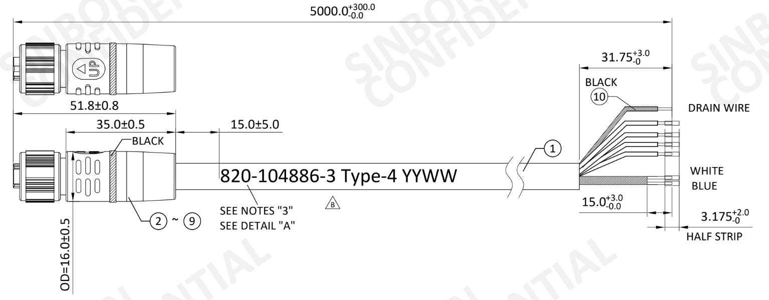
Type 4 (1000BASE-T1) CAD Drawing |
Note
A black shielding drain wire is included for convenient bonding of the braided shield as required. It’s important to note that the drain wire is not connected to any pin in the sensor. The drain wire can be left unconnected unless the user wants to use it for EMI/EMC tests.
Net Name |
Pin No. |
Wire Color |
Type-4, Base 1000 T1 |
Twisted with |
Color (Display) |
|---|---|---|---|---|---|
VCC |
1 |
Red |
18 AWG |
NA |
|
GROUND |
7 |
Black |
18 AWG |
NA |
|
MULTIPURPOSE_IO |
3 |
Purple |
28 AWG |
NA |
|
SYNC_PULSE _IN |
2 |
Yellow |
28 AWG |
NA |
|
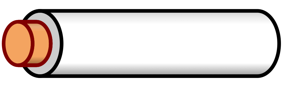
Ethernet BI_DA+ |
12 |
Blue |
26 AWG |
White |
|
Ethernet BI_DA- |
11 |
White |
26 AWG |
Blue |
|
Warning
Ouster is not responsible for any errors in wiring as a result of bypassing the Interface Box and this activity may result in voiding of your warranty if it results in damage to the sensor.
The following guidelines for direct cable connection assume use of the Ouster-provided 24V 1.5A power supply. Ouster cannot be held responsible for damage to the device if an alternate is used.