Sensor Data
Coordinate Frames and XYZ Calculation
Ouster defines two coordinate frames:
The Lidar Coordinate Frame follows the Right Hand Rule convention and is a point cloud-centric frame of reference that is the simplest frame in which to calculate and manipulate point clouds. The X-axis points backwards towards the external connector, which is an unintuitive orientation that was deliberately chosen to meet the following criteria:
Data frames split at the back of the sensor i.e. the external connector
Data frames start with the azimuth angle equal to 0°
All point cloud features including setting an azimuth window and phase locking are defined in the Lidar Coordinate Frame.
The Sensor Coordinate Frame follows the Right Hand Rule convention and is a mechanical housing-centric frame of reference that follows robotics convention with X-axis pointing forward. Ouster-provided drivers and visualizers represent data in the Sensor Coordinate Frame.
Note
All Ouster coordinate frames follow the Right Hand Rule, allowing for standard 3D transformation matrix math to convert between them. For multi-sensor systems that require calibration, this Linear Algebra-based approach can be convenient. However, customers with single-sensor systems may find it more intuitive to stay in the Lidar Coordinate Frame and take arithmetic shortcuts.
Lidar Coordinate Frame
The Lidar Coordinate Frame is defined at the intersection of the lidar axis of rotation and the lidar optical midplane (a plane parallel to Sensor Coordinate Frame XY plane and coincident with the 0° elevation beam angle of the sensor).
- The Lidar Coordinate Frame axes are arranged with:
positive X-axis pointed at encoder angle 0° and the external connector
positive Y-axis pointed towards encoder angle 90°
positive Z-axis pointed towards the top of the sensor
The Lidar Coordinate Frame is marked in both diagrams below with XL, YL, and ZL.

Top-down view of Lidar Coordinate Frame
Lidar Range to XYZ
Given the following information, range data may be transformed into 3D cartesian XYZ coordinates in the Lidar Coordinate Frame:
- From a measurement block from the UDP packet:
- From the GET /api/v1/sensor/metadata/beam_intrinsics HTTP Command:
beam_to_lidar_transform[3] valuebeam_altitude_anglesarraybeam_azimuth_anglesarray
The corresponding 3D point can be computed by
![r &= \texttt{range\_mm} \\
|\vec{n}| &= \sqrt{(beam\_to\_lidar[0,3])^2 + (beam\_to\_lidar[2,3])^2} \\
r &= |\vec{r'}| + |\vec{n}| \\
\theta_{encoder} &= 2\pi \cdot \left ( 1 - \frac{\texttt{measurement\ ID}}{\texttt{scan\_width}}\right ) \\
\theta_{azimuth} &= -2\pi \frac{\texttt{beam\_azimuth\_angles[i]}}{360} \\
\phi &= 2\pi \frac{\texttt{beam\_altitude\_angles[i]}}{360} \\
\\
x &= (r-|\vec{n}|) \cos\left(\theta_{encoder} + \theta_{azimuth}\right) \cos(\phi) + (beam\_to\_lidar[0,3]) \cos\left(\theta_{encoder}\right) \\
y &= (r-|\vec{n}|) \sin\left(\theta_{encoder} + \theta_{azimuth}\right) \cos(\phi) + (beam\_to\_lidar[0,3]) \sin\left(\theta_{encoder}\right) \\
z &= (r-|\vec{n}|) \sin(\phi) + (beam\_to\_lidar[2,3]) \\](../../../_images/math/0857297bc313f2c64a8250c38e96e5ecc98cea6c.png)

Side view of Lidar Coordinate Frame
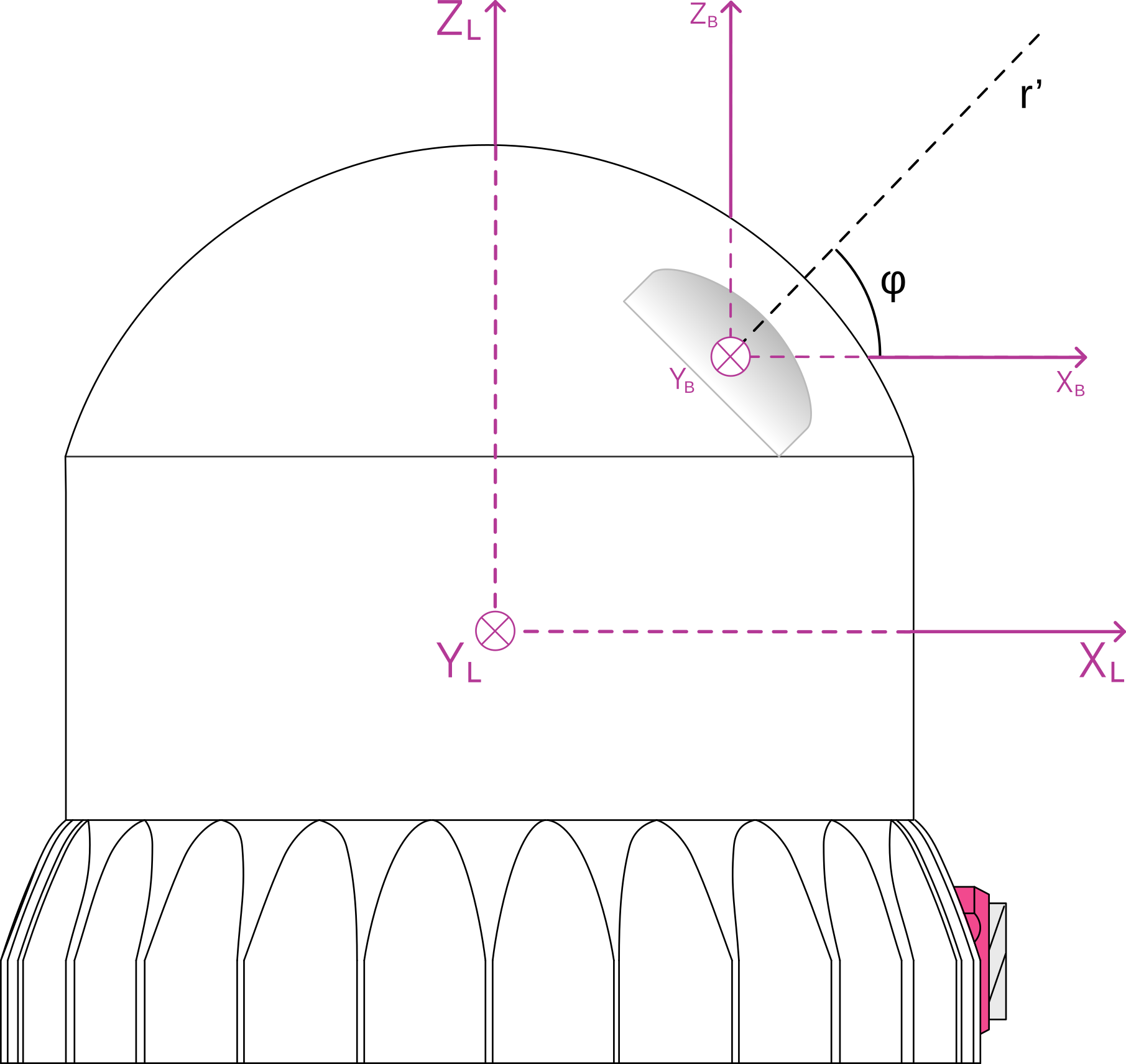
Side view of an OSDome Lidar Coordinate Frame
Sensor Coordinate Frame
The Sensor Coordinate Frame is defined at the center of the sensor housing on the bottom, with the X-axis pointed forward, Y-axis pointed to the left and Z-axis pointed towards the top of the sensor. The external connector is located in the negative x direction. The Sensor Coordinate Frame is marked in the diagram below with XS, YS, ZS.

Top-down view of Sensor Coordinate Frame

Side view of Sensor Coordinate Frame
Combining Lidar and Sensor Coordinate Frame
The Lidar Coordinate Frame’s positive X-axis (0 encoder value) is opposite the Sensor Coordinate Frame’s positive X-axis to center lidar data about the Sensor Coordinate Frame’s positive X-axis. A single measurement frame starts at the Lidar Coordinate Frame’s 0° position and ends at the 360° position. This is convenient when viewing a “range image” of the Ouster Sensor measurements, allowing the “range image” to be centered in the Sensor Coordinate Frame’s positive X-axis, which is generally forward facing in most robotic systems.
The Ouster Sensor scans in the clockwise direction when viewed from the top, which is a negative rotational velocity about the Z-axis. Thus, as encoder ticks increase from 0 to 90,111, the actual angle about the Z-axis in the Lidar Coordinate Frame will decrease.
Lidar Intrinsic Beam Angles
The intrinsic beam angles for each beam may be queried with a HTTP command GET /api/v1/sensor/metadata/beam_intrinsics to provide an azimuth and elevation adjustment offset to each beam. The azimuth adjustment is referenced off of the current encoder angle and the elevation adjustment is referenced from the XY plane in the Sensor and Lidar Coordinate Frames.
Lidar Range Data To Sensor XYZ Coordinate Frame
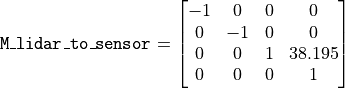
For applications that require calibration against a precision mount or use the IMU data (Inertial Measurement Unit) in combination with the lidar data, the XYZ points should be adjusted to the Sensor Coordinate Frame. This requires a Z translation and a rotation of the X,Y,Z points about the Z-axis. The Z translation is the height of the lidar aperture stop above the sensor origin, which varies depending on the sensor you have, and the data must be rotated 180° around the Z-axis. This information can be queried via HTTP in the form of a homogeneous transformation matrix in row-major ordering.
Example JSON formatted query using the HTTP command GET /api/v1/sensor/metadata/lidar_intrinsics:
{
  "lidar_to_sensor_transform": [-1, 0, 0, 0, 0, -1, 0, 0, 0, 0, 1, 38.195, 0, 0, 0, 1]
}
Which corresponds to the following matrix
IMU Data To Sensor XYZ Coordinate Frame
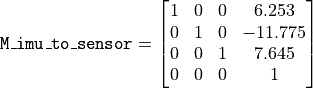
The IMU is slightly offset in the Sensor Coordinate Frame for practical reasons. The IMU origin in the Sensor Coordinate Frame can be queried over HTTP command in the form of an homogeneous transformation matrix in row-major ordering.
Example 1- Expected response for HTTP command GET /api/v1/sensor/metadata/imu_intrinsics when using Gen1 OS1 (all revisions), Gen2 OS01 (all revisions) and Gen2 OS2 (top-level revisions A, B, C)
{
  "imu_to_sensor_transform": [1, 0, 0, 6.253, 0, 1, 0, -11.775, 0, 0, 1, 7.645, 0, 0, 0, 1]
}
Which corresponds to the following matrix
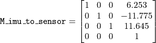
Example 2- Expected response for HTTP command GET /api/v1/sensor/metadata/imu_intrinsics when using Gen2 OS2 (top-level revisions D and higher)
{
  "imu_to_sensor_transform": [1, 0, 0, 6.253, 0, 1, 0, -11.775, 0, 0, 1, 11.645, 0, 0, 0, 1]
}
Which corresponds to the following matrix
Lidar Data Packet Format
Note
For all users transitioning from firmware version 3.0 to 3.1, please note that LEGACY profile has been deprecated and will not be available for use in a future firmware release. Please refer to the current default profile on the sensor i.e.., RNG19_RFL8_SIG16_NIR16 Return Profile.
With firmware version v3.1 and above, users will have the option to switch between different lidar data packet formats as shown below.
Configurable Data Packet Format
LEGACY Data Packet Format (Deprecated - Not Available starting FW v3.1)
By default, the data packet format will be set to RNG19_RFL8_SIG16_NIR16 Return Profile for Firmware v3.0 and later.
Dual Returns
The dual return feature allows the sensor to output up to 2 lidar returns, enabling better performance in scenarios with semi-transparent obscurants, such as rain, fog, or chain-link fences. In these scenarios, the strongest and second strongest returns are required to see both the semi-transparent object, as well as whatever may lie behind it.
Return Order
The following return_order can be set STRONGEST_TO_WEAKEST (Default), NEAREST_TO_FARTHEST and FARTHEST_TO_NEAREST.
When a DUAL UDP profile is selected, the sensor returns the two strongest returns for each radial beam. The order in which these two returns appear depends on the setting of the return order which has the following possible values.
STRONGEST_TO_WEAKEST: The strongest of the two returns is the first return and the next strongest (or the weakest of these two returns) follows. This return order prioritizes the points based on their signal strength, with the strongest signals coming first. This can be useful in applications where identifying the most prominent or reflective objects is crucial.
FARTHEST_TO_NEAREST: The farthest of the two returns is the first return and the next strongest and therefore nearest of the two strongest returns follows. This return order organizes the points based on their distance from the lidar sensor, with the farthest points listed first. It is valuable when the focus is on understanding the spatial distribution of objects in the sensor’s field of view.NEAREST_TO_FARTHEST: The nearest of the two strongest returns is the first return and the farthest of the two strongest returns follows. This return order prioritizes the closest point, listing it first. This order can be beneficial in applications where identifying nearby obstacles or points of interest is critical.
The choice of return_order depends on the application. For example, in obstacle detection scenarios, NEAREST_TO_FARTHEST might be preferred for identifying nearby objects, whilst in mapping applications FARTHEST_TO_NEAREST could be more suitable for capturing the spatial layout of the environment.
Configurable Data Packet Format
Different options for udp_profile_lidar maintain a uniform packet structure, which is described in detail below.
Lidar Data Format
Each data packet consists of Packet Header, Measurement Header, Channel Data Blocks and Packet Footer. The packet rate is dependent on the lidar mode. Words are 32 bits in length and little endian.
By default, lidar UDP data is forwarded to Port 7502. Please refer to the HTTP API Reference Guide section of this manual for more information on setting this parameter. Alternately, this mode can also be configured via the Web Interface.
Packet layout
Packet Header [256 bits]
Packet type [16 bit unsigned int] - Identifies lidar data vs. other packets in stream. Packet Type is 0x1 for Lidar packets.
Frame ID [16 bit unsigned int] - Index of the lidar scan, increments every time the sensor completes a rotation, crossing the zero azimuth angle.
Init ID [24 bit unsigned int] - Initialization ID. Updates on every reinitialization, which may be triggered by the user or an error, and every reboot. This value may also be obtained by running the HTTP command GET /api/v1/sensor/metadata/sensor_info.
Serial No [40 bit unsigned int] - Serial number of the sensor. This value is unique to each sensor and can be found on a sticker affixed to the top of the sensor. In addition, this information is also available on the Sensor Web UI and by reading the field
prod_snfrom GET /api/v1/sensor/metadata/sensor_info.Shot limiting status [4 bit unsigned int] - Indicates the shot limiting status of the sensor. Different codes indicates whether the sensor is in Normal Operation or in Shot Limiting. Please refer to Shot Limiting section for more details.
Shutdown Status [4 bit unsigned int] - Indicates whether thermal shutdown is imminent. Please refer to Shot Limiting section for more details.
Shot limiting Countdown [8 bit unsigned int] - Countdown from 30s to indicate when shot limiting is imminent. Please refer to Shot Limiting section for more details.
Shutdown Countdown [8 bit unsigned int] - Countdown from 30s to indicate that thermal shutdown is imminent. Please refer to Shot Limiting section for more details.
- Alert Flags [8 bit unsigned int]:
bit [0-5]: alert_cursors (Increments sequentially every time a new alert is active or an alert is cleared. At this time users can query GET /api/v1/sensor/alerts to understand which alert was activated or cleared).
bit [6]: cursor_overflow (true if cursor overflows, cleared when GET /api/v1/sensor/alerts is read. cursor_overflow turns on whenever alert_cursors goes from 63->0, and stays on until the next time GET /api/v1/sensor/alerts is called).
bit [7]: alerts_active (true if ANY alerts are active).
Column Header Block [96 bits]
Timestamp [64 bit unsigned int] - Timestamp of the measurement in nanoseconds.
Measurement ID [16 bit unsigned int] - Sequentially incrementing measurement counting up from 0 to 511, or 0 to 1023, or 0 to 2047 depending on lidar_mode.
Status [1 bit unsigned int] - Indicates validity of the measurements. Status is 0x01 for valid measurements. Status is 0x00 for dropped or disabled columns.
Channel Data Blocks [Varies based on channel data profile]
The size and the structure of the channel data block varies based on the configurable data packet format chosen by the user. More information on each of these options are described below in the following sections.
Packet Footer [256 bits]
Reserved [192 bits]
E2E CRC [64 bits] - This covers the end to end cyclic redundancy check (CRC) on the entire data packet. For more details refer to E2E CRC64 calculation parameters.
Configurable Data Packet Configuration
E2E CRC64 calculation parameters
The CRC64 is calculated on the received UDP lidar packet payload bytes, in the same received bit order, without the encoded CRC64 value [I.E. excluding the last 64 bits of the received lidar packet], and by using the following CRC algorithm calculation parameters:
CRC Result Width |
64 bits |
Polynomial |
0x42f0e1eba9ea3693 |
Initial Value |
0xffffffffffffffff |
Input data reflected |
Yes |
Result data reflected |
Yes |
XOR Value |
0xffffffffffffffff |
Since the value of the CRC64 in the received lidar packet is encoded as a Little-Endian hex value; you will have to reverse the CRC64 bytes (last 8 bytes of the lidar packet) before comparing them with the hex value of the calculated CRC64 that is based on the received lidar packet bytes.
Channel Data Profiles
This section describes the different channel data profile options that are available to the users as part of the configurable data packet format. Each of these data profiles can be selected by setting the configuration parameter udp_profile_lidar to one of the following options:
More details on how to set the configuration parameters are described in the HTTP API Reference Guide portion of this Firmware User Manual.
Note
Calibrated reflectivity has certain hardware requirements. Please refer to the Calibrated Reflectivity section for more details.
Description |
|||
Profiles |
|
|
|
Words per pixel |
3 |
1 |
4 |
Range RET1 |
19 bits |
15 bits |
19 bits |
Reflectivity RET1 |
8 bits |
8 bits |
8 bits |
Range RET2 |
Not Available |
Not Available |
19 bits |
Reflectivity RET2 |
Not Available |
Not Available |
8 bits |
Signal RET1 |
16 bits |
Not Available |
16 bits |
Signal RET2 |
Not Available |
Not Available |
16 bits |
NIR |
16 bits |
8 bits |
16 bits |
RNG19_RFL8_SIG16_NIR16 Return Profile
The data packet format for all sensors by default is set to RNG19_RFL8_SIG16_NIR16 i.e., Single Return Profile. This channel data profile can also be activated from a different setting by changing the configuration parameter udp_profile_lidar to RNG19_RFL8_SIG16_NIR16.
This channel data profile is identical to the channel data block present in previously available LEGACY format (Deprecated), but makes use of the configurable data packet format. Users looking to take advantage of the configurable data packet format can use this profile in place of LEGACY. The channel data profile for this is described below.
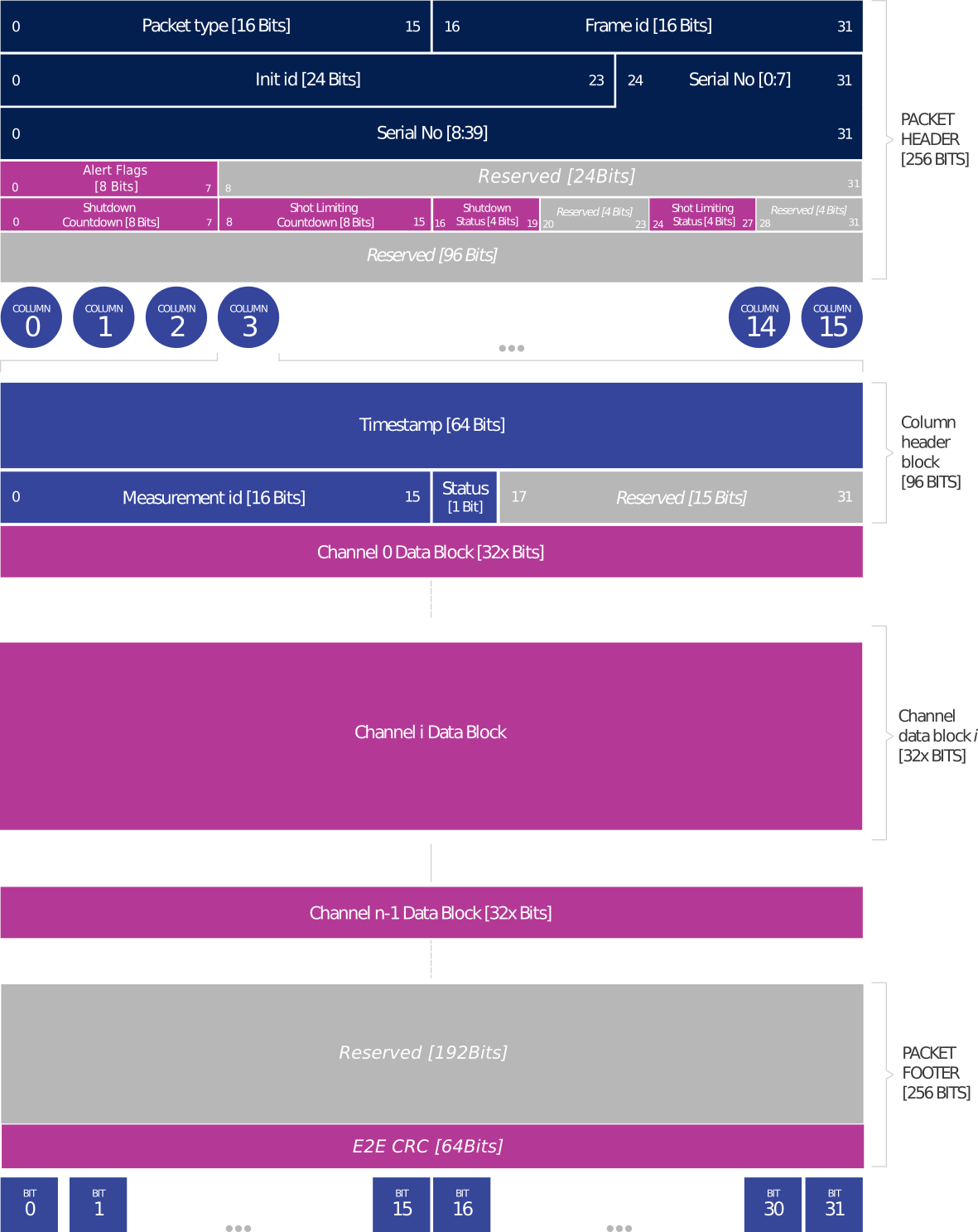
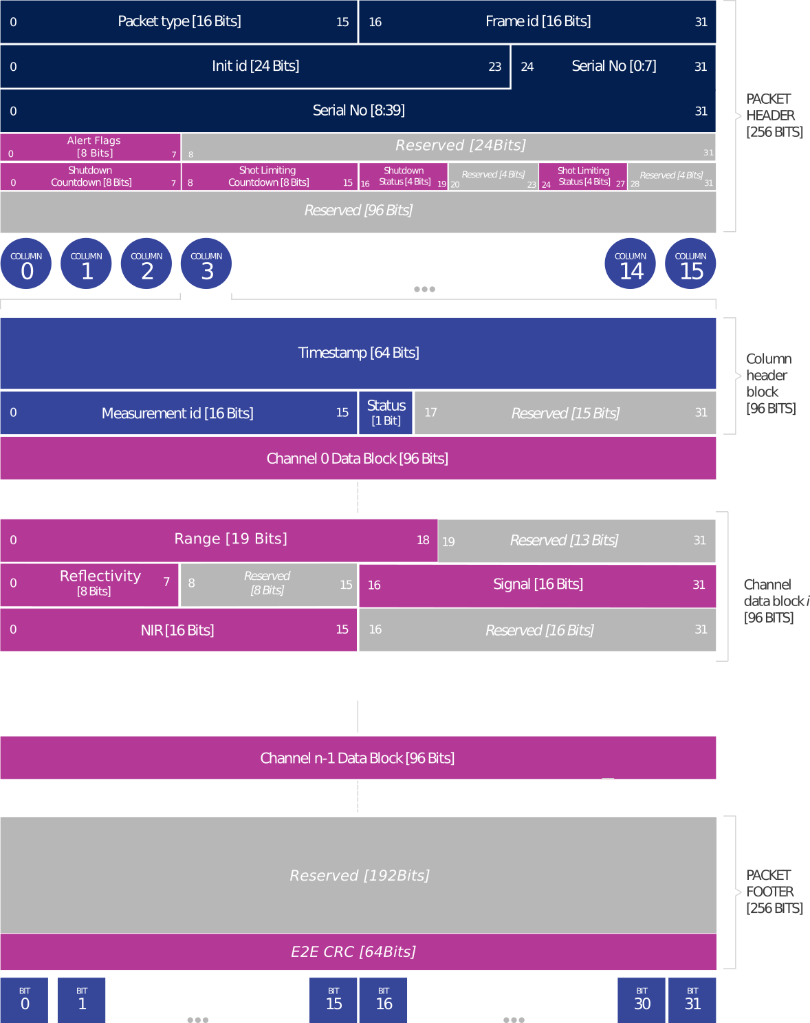
Channel Data Blocks [96 bits each for RNG19_RFL8_SIG16_NIR16 profile]
For RNG19_RFL8_SIG16_NIR16 profile the channel data block consists of 3 words to accommodate data for porting over the LEGACY profile (Deprecated) to configurable Data Packet format. Only a single return will be made available to the user.
Range [19 bit unsigned int] - Range in millimeters, discretized to the nearest 1 millimeters with a maximum range of 524m. Note that range value will be set to 0 if out of range or if no detection is made.
Calibrated Reflectivity [8 bit unsigned int] - Sensor Signal Photons measurements are scaled based on measured range and sensor sensitivity at that range, providing an indication of target reflectivity.
Signal Photons [16 bit unsigned int] - Signal intensity photons in the signal return measurement are reported.
Near Infrared Photons [16 bit unsigned int] - NIR photons related to natural environmental illumination are reported.
Single Return Configuration
RNG15_RFL8_NIR8 Return Profile
This channel data profile can be activated by setting the configuration parameter udp_profile_lidar to RNG15_RFL8_NIR8.
This channel data profile is especially useful to users who are looking to adopt a channel data profile to fit with limited compute capabilities. The data rate and data packet size when using this profile is smaller compared to the other channel data profile options that are available.
The channel data profile for this is described below.
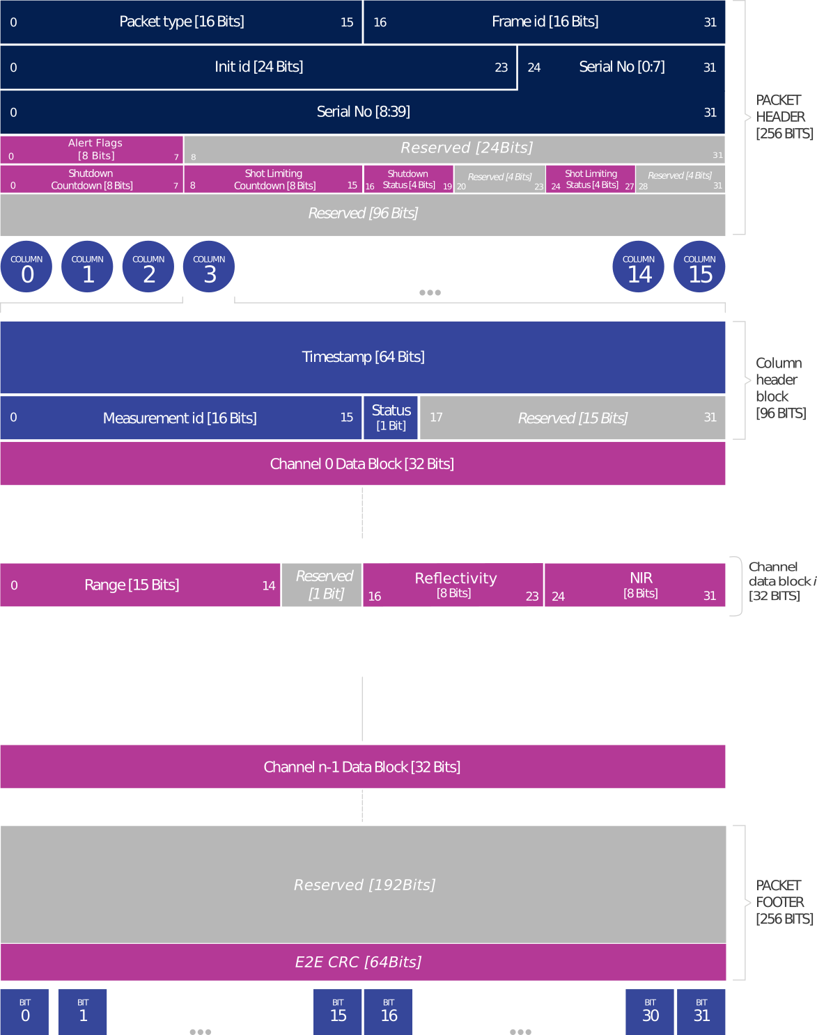
Channel Data Blocks [32 bits each for RNG15_RFL8_NIR8 profile]
For the RNG15_RFL8_NIR8 profile the channel data block consists of only 1 word to accommodate data for optimizing information at a low data rate. Only a single return is made available to the user.
Range [15 bit unsigned int] - Range scaled down by a factor of 8 mm, for a maximum range of (2^15*8) = 262 m in 15 bits. Note: The range value will be set to 0 if out of range or if no detection is made.
Calibrated Reflectivity [8 bit unsigned int] - Sensor Signal Photons measurements are scaled based on measured range and sensor sensitivity at that range, providing an indication of target reflectivity.
Near Infrared Photons [8 bit unsigned int] - NIR photons related to natural environmental illumination are reported. Measurements are taken similar to other data profiles (Single Data Profile and Dual Return Profile) but it is scaled down by a factor of 16.
Low Data Rate Configuration
RNG19_RFL8_SIG16_NIR16_DUAL Return Profile
This channel data profile can be activated by setting the configuration parameter udp_profile_lidar to RNG19_RFL8_SIG16_NIR16_DUAL.
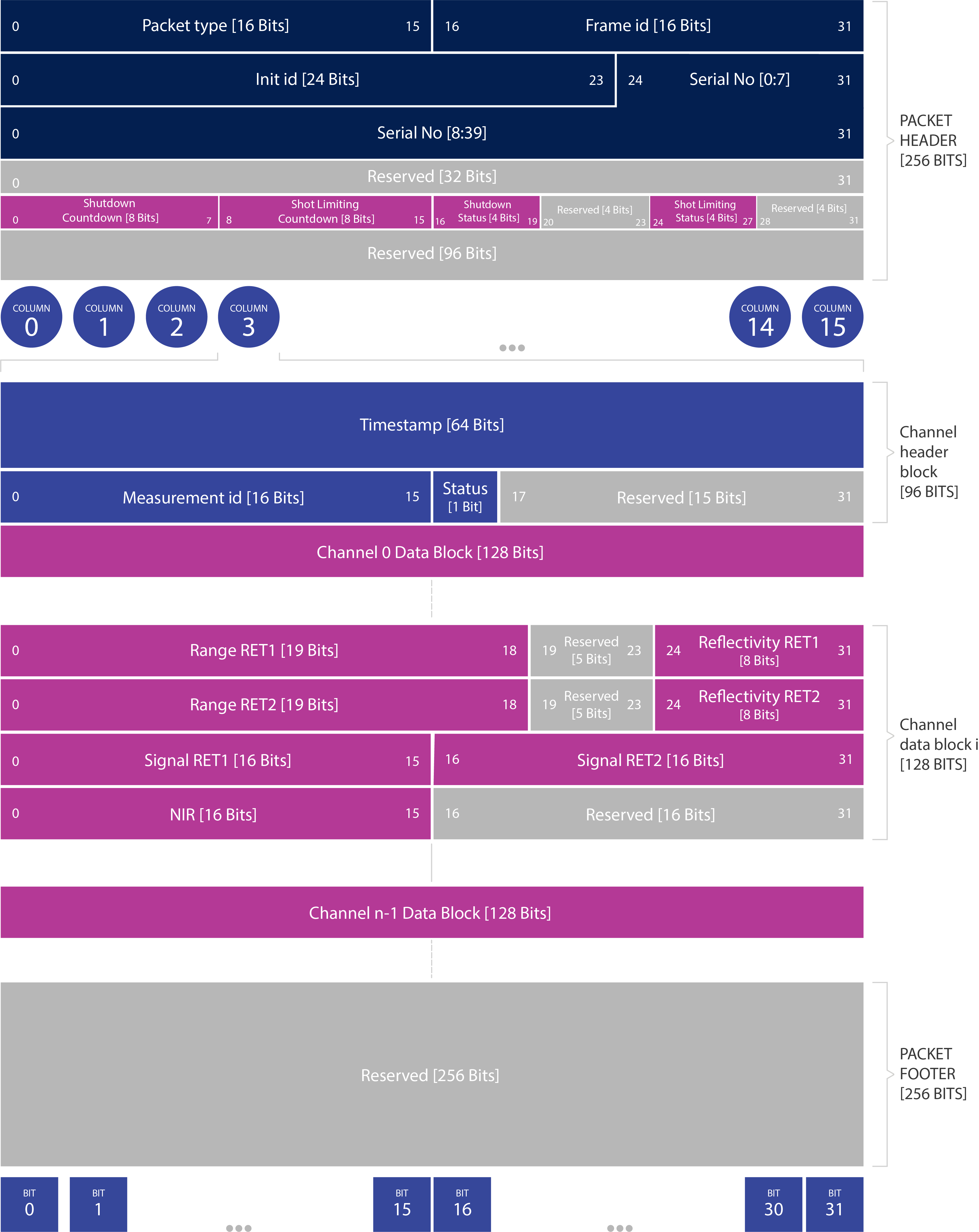
Channel Data Blocks [128 bits each for RNG19_RFL8_SIG16_NIR16_DUAL profile]
For RNG19_RFL8_SIG16_NIR16_DUAL profile the channel data block consists of 4 words to accommodate data for two lidar returns.
Range RET1/2 [19 bit unsigned int] - range in millimeters, discretized to the nearest 1 millimeters with a maximum range of 524m. Note that range value will be set to 0 if out of range or if no detection is made.
Calibrated Reflectivity RET1/2 [8 bit unsigned int] - Sensor Signal Photons measurements are scaled based on measured range and sensor sensitivity at that range, providing an indication of target reflectivity.
Signal Photons RET1/2 [16 bit unsigned int] - Signal intensity photons in the signal return measurement are reported.
Near Infrared Photons [16 bit unsigned int] - NIR photons related to natural environmental illumination are reported.
Dual Return Data Packet Configuration
FUSA_RNG15_RFL8_NIR8_DUAL Return Profile
Setting udp_profile_lidar to value FUSA_RNG15_RFL8_NIR8_DUAL activates the Functional Safety data packet format. This packet format will be expanded periodically with every firmware release to report flags, error checking mechanisms, and alerts necessary for a functionally safe system. This packet format has a different header and footer structure.
Note
Rev7 sensor with FW v3.1 is a minimum requirement to use this lidar packet format. This profile is expanded periodically and it does not mean that the sensor is actually FUSA certified.
Lidar Data Format
When udp_profile_lidar is set to FUSA_RNG15_RFL8_NIR8_DUAL, each data packet consists of Packet Header, Measurement Header, Channel Data Blocks and Packet Footer. The packet rate is dependent on the lidar mode. Words are 32 bits in length and little endian. By default, lidar UDP data is forwarded to Port 7502. Please refer to HTTP API Reference Guide section of this manual for more information on configuring this parameter. Alternatively this mode can also be configured via the web interface.
"udp_profile_lidar=FUSA_RNG15_RFL8_NIR8_DUAL"
This profile is meant to allow the sensor to provide an output up to 2 returns at a low data rate. Refer to Return Order for more information.
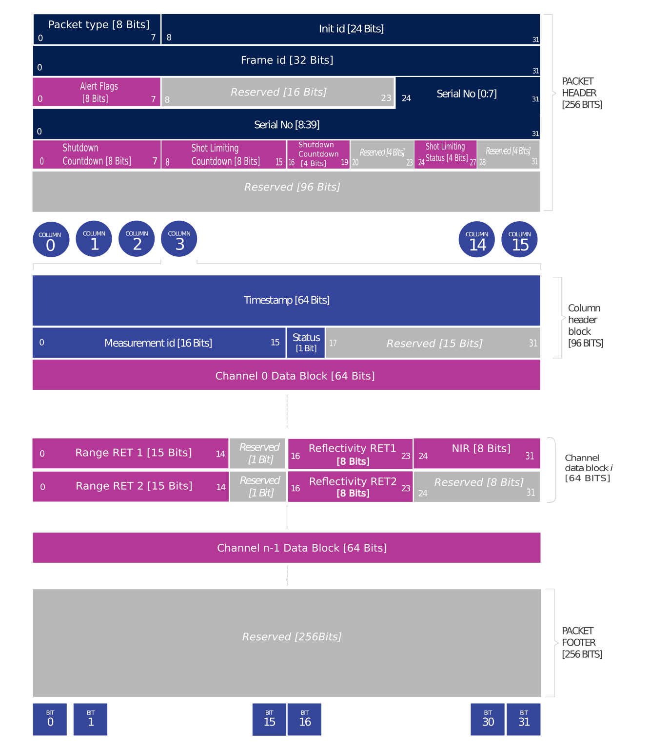
Packet layout
For FUSA_RNG15_RFL8_NIR8_DUAL profile the channel data block consists of 64 bits to accommodate data for the multiple returns. A total of up to two returns will be made available to the user.
Packet Header [256 bits]
Packet type [8 bit unsigned int] - Identifies lidar data vs. other packets in stream. Packet Type is 0x1 for Lidar packets.
Init ID [24 bit unsigned int] - Initialization ID. Updates on every reinitialization, which may be triggered by the user or an error, and every reboot. This value may also be obtained by running the HTTP command GET /api/v1/sensor/metadata/sensor_info.
Frame ID [32 bit unsigned int] - Index of the lidar scan, increments every time the sensor completes a rotation, crossing the zero azimuth angle.
Serial No [40 bit unsigned int] - Serial number of the sensor. This value is unique to each sensor and can be found on a sticker affixed to the top of the sensor. In addition, this information is also available on the Sensor Web UI and by reading the field
prod_snfrom GET /api/v1/sensor/metadata/sensor_info.Alert Flags [8 bit unsigned int]:
bit [0-5]: alert_cursors (Increments sequentially everytime a new alert is active. At this time users can query GET /api/v1/sensor/alerts to understand which alert was activated).
bit [6]: cursor_overflow (true if cursor overflows, cleared when GET /api/v1/sensor/alerts is read. cursor_overflow turns on whenever alert_cursors goes from 63->0, and stays on until the next time GET /api/v1/sensor/alerts is called).
bit [7]: alerts_active (true if ANY alerts are active).
Shutdown Countdown [8 bit unsigned int] - Countdown from 30s to indicate that thermal shutdown is imminent. Please refer to Shot Limiting section for more details.
Shot limiting Countdown [8 bit unsigned int] - Countdown from 30s to indicate when shot limiting is imminent. Please refer to Shot Limiting section for more details.
Shutdown Status [4 bit unsigned int] - Indicates whether thermal shutdown is imminent. Please refer to Shot Limiting section for more details.
Shot limiting status [4 bit unsigned int] - Indicates the shot limiting status of the sensor. Different codes indicate whether the sensor is in Normal Operation or in Shot Limiting. Please refer to Shot Limiting section for more details.
Column Header Block [96 bits]
Timestamp [64 bit unsigned int] - Timestamp of the measurement in nanoseconds.
Measurement ID [16 bit unsigned int] - Sequentially incrementing measurement counting up from 0 to 511, or 0 to 1023, or 0 to 2047 depending on lidar_mode.
Status [1 bit unsigned int] - Indicates validity of the measurements. Status is 0x01 for valid measurements. Status is 0x00 for dropped or disabled columns.
Channel Data Blocks [64 bits]
Range RET1/2 [15 bit unsigned int] - Range scaled down by a factor of 8 mm, for a maximum range of (2^15*8) = 262 m in 15 bits.
Calibrated Reflectivity RET1/2 [8 bit unsigned int] - Sensor Signal Photons measurements are scaled based on measured range and sensor sensitivity at that range, providing an indication of target reflectivity.
Near Infrared Photons [8 bit unsigned int] - NIR photons related to natural environmental illumination are reported. Measurements are taken similar to other data profiles (Single Data Profile and Dual Return Profile) but it is scaled down by a factor of 16.
Packet Footer [256 bits]
Functional Safety Data Packet Format
Packet Size Calculation
Packet size can be calculated by the following formula:
packet_header_size + columns_per_packet * (measurement_header_size + pixels_per_column * channel_data_block_size) + packet_footer_size
For example:
32 + 16 * (12 + n * s) + 32 bytes
packet_header_size= 32 bytes
columns_per_packet= 16
measurement_header_size= 12 bytesn is
pixels_per_column(correspond to the number of channels: 128 for OS1-128)s is the size of a channel data block (16 bytes for RNG19_RFL8_SIG16_NIR16_DUAL configuration)
packet_footer_size= 32 bytes
The following tables below provide values for packet sizes, packet rates, and data rates for various products and configurations. These tables assume a default azimuth window of 360°. Providing a custom azimuth window can further lower packet rate and data rate. See the Azimuth Window section for details on setting a custom azimuth window.
Product |
Single Return |
Dual Return |
Low Data Rate |
FUSA Low Data Rate Dual Return |
OS-x-32 |
6400 |
8448 |
2304 |
4352 |
OS-x-64 |
12544 |
16640 |
4352 |
8448 |
OS-x-128 |
24832 |
33024 |
8448 |
16640 |
Product |
512x10 |
1024x10, 512x20 |
2048x10, 1024x20 |
OS-x-32 |
320 |
640 |
1280 |
OS-x-64 |
320 |
640 |
1280 |
OS-x-128 |
320 |
640 |
1280 |
Product |
Single Return |
Dual Return |
Low Data Rate |
FUSA Low Data Rate Dual Return |
OS-x-32 |
65.57 |
86.55 |
23.63 |
44.56 |
OS-x-64 |
128.49 |
170.43 |
44.60 |
86.55 |
OS-x-128 |
254.32 |
338.20 |
86.55 |
170.4 |
LEGACY Data Packet Format
Warning
``LEGACY Data Packet Format is Deprecated``.
Please refer to RNG19_RFL8_SIG16_NIR16 Return Profile section which will be the default lidar packet format with firmware v3.0.0 and later. For more information on LEGACY packet format, please visit Downloads and refer to Firmware User Manual v3.0 or prior. For any questions on how to transition from ‘’LEGACY`` profile to RNG19_RFL8_SIG16_NIR16 Return Profile profile, please contact our Field Application Team.
Calibrated Reflectivity
The calibration status is returned with the following format:
{
  "reflectivity":
  {
      "valid": "true: if factory calibrated for better accuracy, false: if not calibrated -- using default
                      values and likely has less accuracy",
      "timestamp": "Date when the calibration has been performed"
  }
}
Please contact your support@ouster.io if you have questions on whether your sensor is hardware-enabled for calibrated reflectivity.
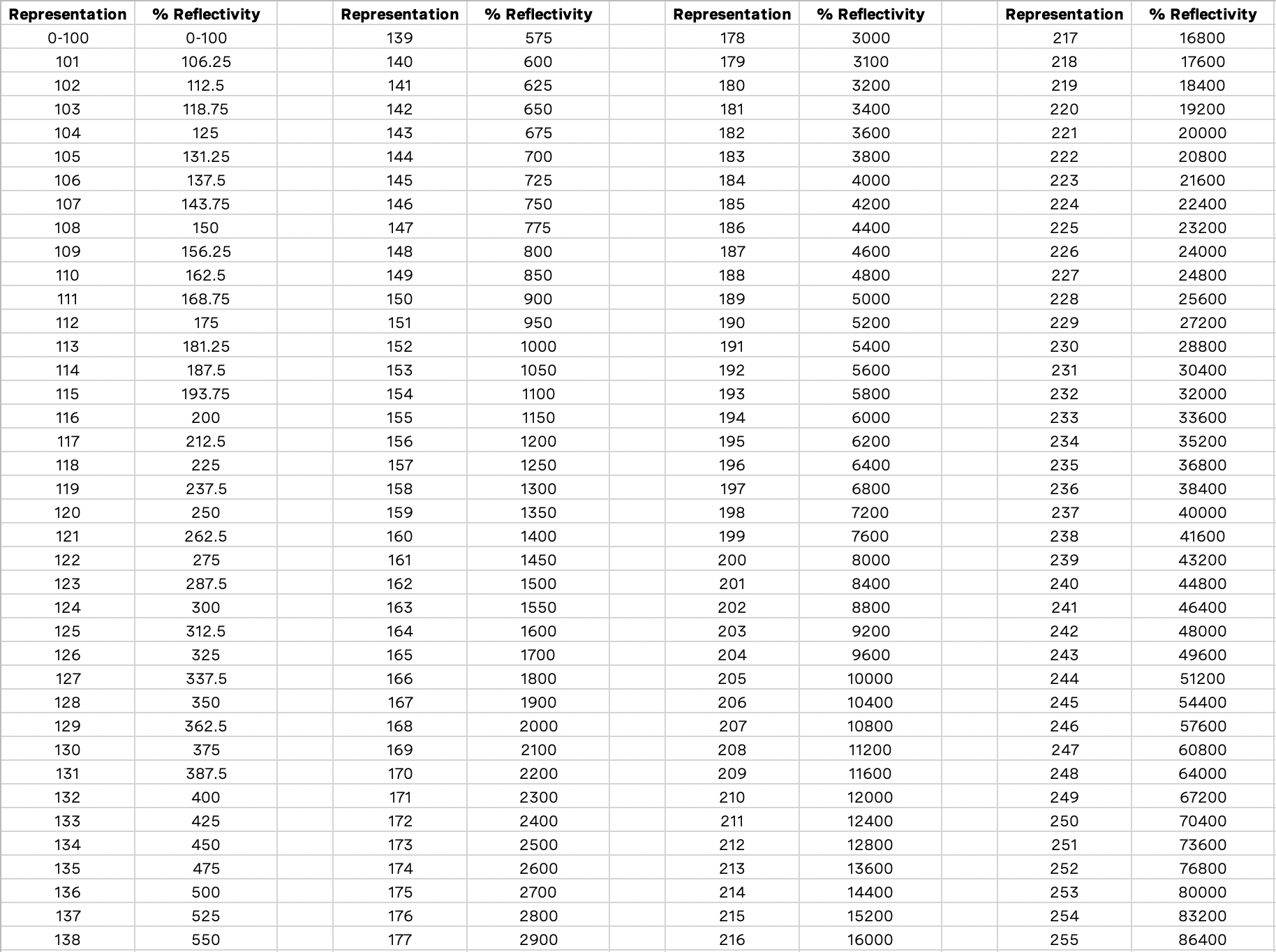
Reflectivity Data Mapping
Reflectivity values between 0-100 are linearly mapped for lambertian targets with values between 0% and 100% reflectivity. Values between 101-255 are mapped as log 2 with linear interpolation between logarithmic points for retroreflective targets. The 255 value corresponds to a retroreflector 864 times stronger than a 100% lambertian target. The charts below show the mapping functions.

% Reflectivity vs Representation
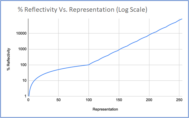
% Reflectivity vs Representation (Log Scale)
IMU Data Format
IMU UDP Packets are 48 Bytes long and by default are sent to Port 7503 at 100 Hz. Data is organized in little endian format.
Note
IMU data format is the same regardless of the lidar data profile selected by the user.
Each IMU data block contains:
IMU Diagnostic Time [64 bit unsigned int] - timestamp of monotonic system time since boot in nanoseconds.
Accelerometer Read Time [64 bit unsigned int] - timestamp for accelerometer time relative to timestamp_mode in nanoseconds.
Gyroscope Read Time [64 bit unsigned int] - timestamp for gyroscope time relative to timestamp_mode in nanoseconds.
Acceleration in X-axis [32 bit float] - acceleration in g.
Acceleration in Y-axis [32 bit float] - acceleration in g.
Acceleration in Z-axis [32 bit float] - acceleration in g.
Angular Velocity about X-axis [32 bit float] - Angular velocity in deg per sec.
Angular Velocity about Y-axis [32 bit float] - Angular velocity in deg per sec.
Angular Velocity about Z-axis [32 bit float] - Angular velocity in deg per sec.
Note that the first timestamp (Words 0,1) is for diagnostics only and is rarely used under normal operation.
The second two timestamps, (Words 2,3) and (Words 4,5), are sampled on the same clock as the lidar data, so should be used for most applications.
Ouster provides timestamps for both the gyro and accelerometer in order to give access to the lowest level information. In most applications it is acceptable to use the average of the two timestamps.
Product |
IMU packet size (Bytes) |
IMU packets per second |
OS1-16 |
48 |
100 |
OS0-32, OS1-32, OS2-32 |
48 |
100 |
OS0-64, OS1-64, OS2-64 |
48 |
100 |
OS0-128, OS1-128, OS2-128 |
48 |
100 |

IMU Packet Format
Configurable IMU Scale
Users now have the capability to access the Full Scale Range (fsr) of the IMU integrated within Ouster sensors. This feature empowers users to adjust the scale of both Accelerometer and Gyroscope measurements captured by the IMU. Scale modifications can be toggled between a default setting termed NORMAL and an enhanced setting labeled EXTENDED. Users have the flexibility to alter the scale of the gyroscope and accelerometer either through GET /api/v1/sensor/metadata/imu_data_format or via the Web UI.
accel_fsr - This configuration parameter facilitates adjustment of the accelerometer scale. It offers two settings:
NORMAL (Default): Digital-output X-, Y-, Z-axis with a full-scale range fixed at ± 2g.
EXTENDED: Digital-output X-, Y-, Z-axis with an expanded full-scale range of ± 16g.
gyro_fsr - This configuration parameter enables modification of the gyroscope scale. It provides two settings:
NORMAL (Default): Digital-output X-, Y-, Z-axis with a full-scale range fixed at ± 250 dps (°/sec).
EXTENDED: Digital-output X-, Y-, Z-axis with a programmable full-scale range of ± 2000 dps (°/sec).
Note
When the scale of the IMU is altered, the measured values within the IMU packets will also be updated accordingly. However, switching to the ‘EXTENDED’ scale may result in a slight loss of precision due to the truncation of the least significant bits (LSB). IMU specifications can be found in the Sensor Datasheet.