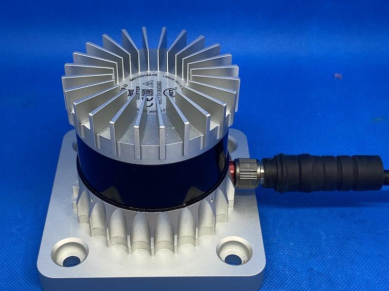
Enhanced Ingress Protection
The Ouster I/O connector system is rated to IP67. When applied as a part of the sensor assembly, the assembly is qualified to IP67 and IP69K.
However, additional measures may be needed in order to preserve the long term Ingress Protection Integrity of the connector system when installed in outdoor locations where sensors are subjected to high levels of precipitation, salt water or aggressive anti-freezing agents and/or large diurnal temperature variations over extended periods of time.
Ruggedness and reliability may be significantly enhanced by the introduction of several measures during the initial installation of the sensor and cabling system.
Ouster provides the Connector Boot Kit (Ouster Part Number 910-014733) to support long term connector ingress protection integrity.
Connector Boot Kit consists of the following components:
0.33 Oz Tube of Dielectric Grease
Ouster 10.5mm Rubber Boot
4”(100mm) Zip tie
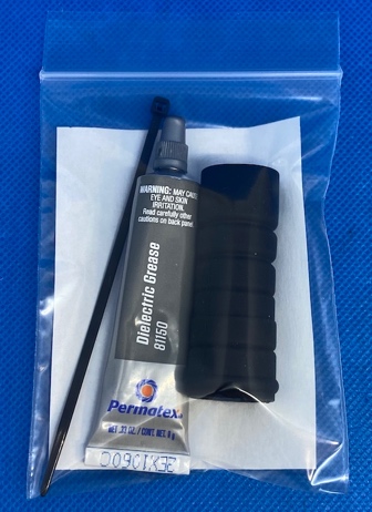
Connector Boot Kit (Ouster Part Number 910-014733)
Note
This kit will be shipped along with every sensor starting September 2022. To purchase this kit individually please contact Ouster Sales for more information.
We will be offering two types of rubber boots for our cables:
A 10.5mm rubber boot (Ouster p/n 820-104403) to be used on existing cables for added protection of the connector outer shell and interconnect area. These boots have been designed to be installed on cables that have already been installed.
An 8.5mm rubber boot (Ouster p/n 820- 104404) is pre-integrated onto an Ouster cable during manufacturing.
Installing the Dielectric Grease Rubber Boot
For the rubber boot installation, the user will need the Connector Boot Kit (Ouster PN: 910-014733). The dielectric grease will be used on the inside of the connector’s collet, and the rubber boot will be installed over the connector to maximize ingress protection.
The installation of the boot is strongly recommended for outdoor applications such as Off-Highway Industrial Equipment, Intelligent Traffic Systems, Automotive/AV applications or fixed surveillance systems where the sensor is mounted in exposed locations with long term harsh environmental conditions.
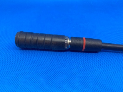
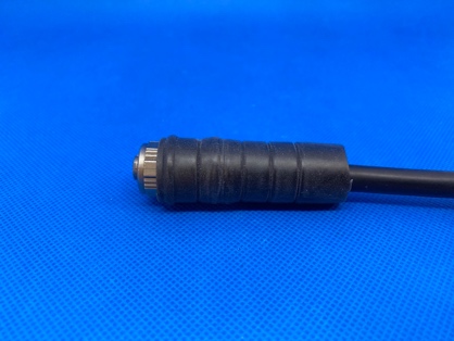
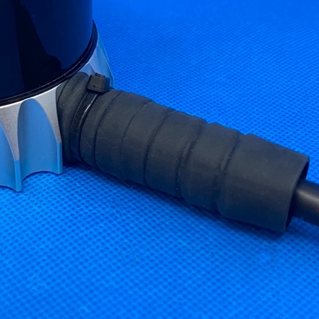
Ouster 10.5mm Rubber Boot (Ouster PN: 820-104403) Installation onto the cable:
The Ouster 10.5mm Rubber boot is designed to be installed over the connector on an existing Ouster cable.
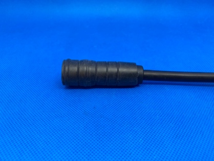
Install the Ouster 10.5mm Rubber boot over the front of the connector as shown below.
Step 1 |
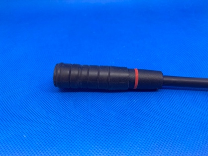
Step 2 |
Step 3 |
Step 4 |
Note
The end of the rubber boot that has the longest section without a concentric rib is the first part to be installed over the plug.
Expect the installation of the rubber boot to require a mild stretching to successfully install on the connector cable.
Dielectric Grease
Dielectric grease is provided in the Connector Boot Kit. Should you need more, any standard Silicone Dielectric Grease available at marine/boating stores is suitable for this application. There are many suppliers of this material.
Warning
DO NOT use anything other than a silicone-based dielectric grease otherwise a significant degradation of the connector O-Rings electrical performance is likely.
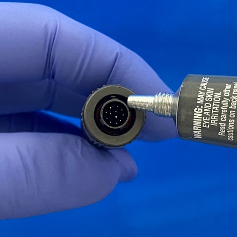
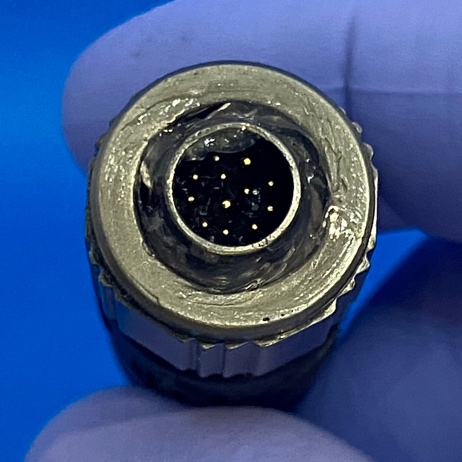
Dielectric Grease Application Part 1 (Cable Plug)
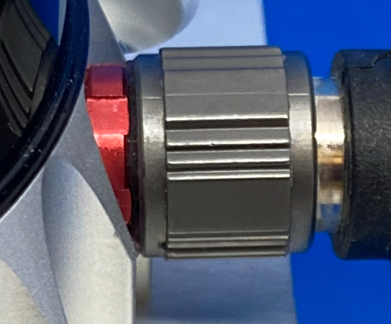
Inject an ample amount of dielectric grease as indicated between the connector body and the locking collet of the connector to ensure there is an adequate seal. Refer to figures shown below.
Do not apply dielectric grease in the pin cavity due to the possibility of hydrolock occurring during mating of the connector pair. This may result in compromising the connector seal.
Dielectric Grease Application |
Dielectric Grease Application |
Note
A slight spillover of dielectric grease from the collet groove is acceptable.
Dielectric Grease Application Part 2 (Sensor Receptacle)
Inject dielectric grease into the channel of the panel mount receptacle between the connector shell and the inner pin carrier.
Apply a thin layer of dielectric grease over the surface of the pin holder to facilitate sealing as shown in the figure below.
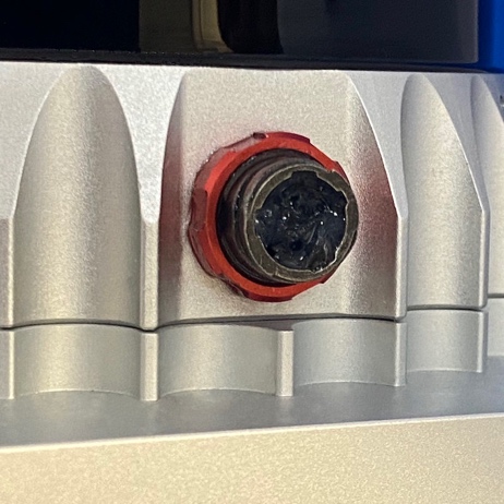
Sensor receptacle dielectric grease application
Connecting the Cable and Securing the Rubber Boot
Plug cable into the sensor with a slight forward and rearward motion to allow air to be displaced by the dielectric grease.
Twist the locking collet on the plug to lock the dielectric-filled connector in place.
A small amount of dielectric grease may be extruded from under the locking collet when the connector is locked, indicating the locking collet cavity is optimally filled with the dielectric grease.
Slide the rubber boot over the connector as shown below and apply the 4” zip tie as indicated as an extra method of securing and sealing the connector.
Final Connector Sealing Step 1 |
Final Connector Sealing Step 2 |
Final Connector Sealing Step 3 |
Note
In user installations where the Ouster baseplate is not utilized, there is limited clearance between the connector collet and the mounting surface, and it may be necessary to release the sensor mounting screws slightly, in order to allow the boot to be slid forward over the connector collet. After the boot has been successfully seated, torque the sensor mounting bolts to the correct torque values.
Ouster Rubber Boot installation is now Complete!!
Additional Ingress Protection: Wrapping the Connector in Self-Vulcanizing Tape
An additional level of environmental protection of the connector maybe provided by the use of self-vulcanizing tape to seal the connector instead of the Rubber Boot.
After installing the Dielectric Grease in the connectors as outlined above in section Installing the Dielectric Grease Rubber Boot, follow on with the application of the tape as indicated by the tape manufacturer’s instructions and the below installation steps for proper application.
Self-Vulcanizing Tape Application Process
We do not provide self-vulcanizing tape with the sensor, but recommend the use of a good quality Self-Vulcanizing tape that is rated for outdoor electrical and/or antenna installations.
Note
The self-vulcanizing tape must be UV resistant. For Example: 3M 2228 Indoor/Outdoor Moisture Sealing tape is a suitable tape. The suitable tape dimensions should be 1”W x 0.065”T or 25mm W x 1,65mm T. Tape thickness should not exceed 0.065” (1.65mm) or the taped connector may interfere excessively with the sensor mounting surface.
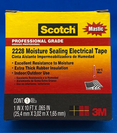
Professional Grade Electrical Tape
Apply the self-vulcanizing tape as indicated and adhere to the following guidelines:
Follow the instructions provided by the tape manufacturer for safe and proper use, taking care to stretch the tape slightly while wrapping the tape to trigger the vulcanizing action.
For example: For Scotch 2228, the requirement is to stretch the tape to ¾ of the original tape width while wrapping the tape.
Note
In user installations where the Ouster Baseplate is not utilized, there is limited clearance between the connector collet and the mounting surface, and it will be necessary to wrap the connector with self-vulcanizing tape prior to mounting Sensor to the mounting surface. In the case where the sensor has already been mounted, it will be necessary to release the sensor mounting screws in order to allow the connector to be wrapped with the Self-Vulcanizing tape. Following the wrapping, remount and re-torque the sensor mounting bolts to the correct torque values.
A length of 10” or 254 mm of the self-vulcanizing tape is adequate to wrap the connector.
Begin the tape wrap on the connector so that the edge of the tape butts up against the side of the sensor base as closely as possible so as to maximize environmental protection of the connector/receptacle pair. See figure below.
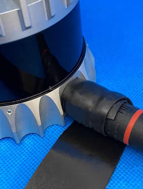
Start of Self-Vulcanizing tape wrap |
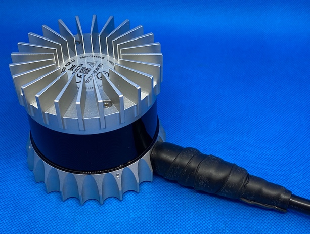
Completed Wrap with Self Vulcanizing tape |
Layer the tape so that each successive wrap overlaps the previous wrap by at least 1/3 of the width of the tape. This will ensure that the successive wraps will be able to reliably vulcanize against the preceding wrap and form a watertight seal.
Terminate the wrap at the far end of the over-mold as indicated.
Warning
Do not attempt to apply a double wrap of the self-vulcanizing tape to the connector since there is limited clearance under the connector when not using the Ouster baseplate and mounting sensor directly to a user mounting structure.
Important NOT to apply more than one layer, making sure to follow to the 1/3 overlap guidance. To ensure adequate clearance between the underside of the tape and the surface upon which the sensor is mounted. Using an excessive amount of tape can result in undue force on the connector due to the interference between the taped connector and the mounting surface.
Removal of Self-Vulcanizing Tape
For maintenance purposes it may be necessary to remove the self vulcanizing tape so that a sensor may be temporarily removed.
The quickest and most efficient method of removing the self vulcanizing tape is to use precision flush-cutting wire cutters as shown below. If proper care is taken during the tape removal, this method eliminates the possibility of damaging the cable jacket, rubber boot or connector.
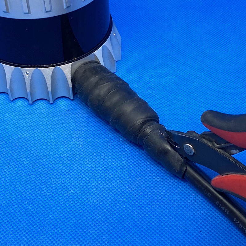
Removal of self-vulcanizing tape (Start) |
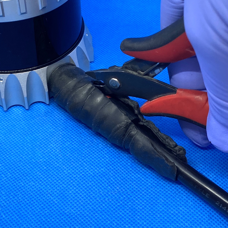
Removal of self-vulcanizing tape (Finish) |
Additional Ingress Protection: Routing the Sensor cable with a Drip Loop
The term “Drip Loop” refers to a technique for dressing the incoming cable immediately before it attaches to the sensor such that it forms a loop below the elevation of the connector on the sensor as shown in the image below:
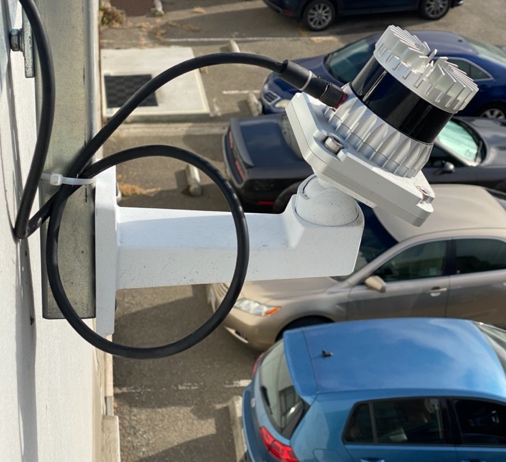
Typical Drip Loop
Drip loops are typically applied to cables routed in outdoor installations where the cable is exposed to condensation or precipitation, and it can act as a gatherer and conduit for water along the outside of the cable jacket.
If care is not taken in the routing of the cable, it can provide a path for water onto the connector terminating the cable, which can result in the connector ingress protection failing over long periods of exposure to the outdoor environment
The function of the drip loop, then, is to shed any precipitation that may have been gathered by the cable along it’s route. If rainwater or other moisture collects on the cable, it naturally flows down to the bottom of the loop, where it drips harmlessly to the ground, rather than down onto the terminating connector. When creating the drip loop, it is important to respect the following guidelines:
Do not violate the minimum cable bend radius directions indicated in the Ouster Sensor manual.
Ensure that the drip loop is adequately secured to the cable support structure so that the cable is not damaged by movement under the influence of wind or the aggregation of snow onto the loop.