Mechanical Interface
Included Components
- The OS2 is shipped with the following items:
OS2-128, OS2-64, or OS2-32
Sensor to interface box cable/connector
Interface Box and 24V AC/DC power supply (2 meters)
RJ45 cable (1 meter)
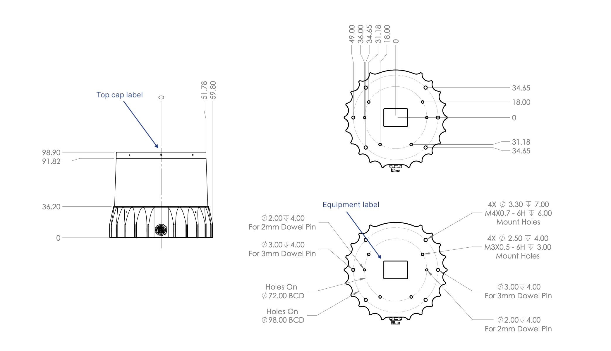
Baseplate Mount
Sensor Components
Downloadable CAD files for the OS2 can be found online at Ouster Download Page
Warning
The water ingress protection rating for the sensor is only valid if the I/O cable is plugged into the panel mount connector on the base of the sensor, and the locking collet rotated past the détente click to the properly locked condition i.e past the détente position. The cable and plug are an element of the sensor ingress protection system. Without the connected cable the ingress protection rating may be compromised. Bending the cable at a sharp angle directly after egress from the plug over mold should also be avoided. Sharp bends and high axial stresses on the cable immediately adjacent to the plug over mold may create a moisture ingress path into the connector. Please note the cable minimum bend radius requirements below:
Mounting Guidelines
Our sensors ship with modular mounting options. The sensor can be mounted in any orientation. Proper mounting will ensure optimal sensor performance, reducing noise from vibration and providing efficient heat dissipation.
Mount to a material with high thermal conductivity. The following are recommended aluminum alloys and their thermal conductivity:
6061: 167 W/m-K
7075: 130 W/m-K
2024: 121 W/m-K
Ensure interfaces are clean and free from debris.
M3 screws are recommended for mounting the sensor. The screw hole pattern in presented in the Sensor drawing above Sensor Components.
Torque bolts appropriately for the mount material and bolts. A torque of 146cNm is recommended for a2 stainless steel screws.
Use TIM (Thermal Interface Material) for any irregular or unmachined surfaces.
Do not overconstrain the sensor if mounting to both the top and the bottom.
Use a thermally conductive pad to ensure good conductivity while not over constraining.
Ensure your implementation maintains the base and top of the sensor at no greater than 25ºC above ambient with an ambient less than 50ºC.
The shape of any heatsink should maximize the surface area for free and forced convection while being thick enough to allow the heat to conduct through the material.
If you have questions about your specific mounting situation please contact the Ouster at support@ouster.io.
Operating Temperatures
Thermal requirements specific to Rev 06 are listed below. The sensor has three operating states in order to manage high temperatures: Active, Shot Limiting, or Inactive. In the standard Active state the sensor will perform to the range and precision specifications of the datasheet. When the sensor reaches a certain temperature (see table below for reference), it enters Shot Limiting state and issues an alert. In Shot Limiting state, the sensor reduces power to the lasers in order to reduce the thermal load. While in this state, sensor range and precision may degrade by up to 20%. When the sensor reaches the maximum operating temperature specified below, the sensor may become Inactive and shut off.
Please contact support@ouster.io with your sensor serial number to find out your sensor revision.
Convective Air Temp with Radial Heatsink and Standard Base |
|
|---|---|
Max temp before shot limiting |
55ºC |
Temp that shot limiting saturated (sensor may turn off above this temperature) |
61ºC |