Sensor Operations
Typical Sensor Operation
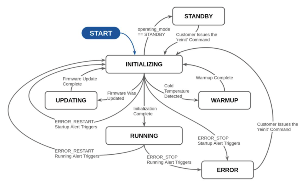
Described below is the typical sensor state machine operation. When the sensor is powered ON, the sensors start in the initialization phase.
Operating State |
Description |
|---|---|
Warm-up |
If the sensor detects that its environmental temperature is low it will attempt to self-heat in a warmup state (Cold Start) before entering a normal operating state. |
Initializing |
Startup of Ouster Lidar. |
Updating |
Only remains in this state temporarily to update the firmware. |
Error |
If an exception is thrown during initialization or running state, the lidar logs the error. |
OFF |
Ouster Lidar shut off. |
Running |
Sensor has completed initialization phase and is now running. |
Standby |
User enabled low power operating mode of the sensor. |
Sensor Telemetry
Sensor telemetry refers to sensor system state information that changes with time i.e., temperature, voltage, etc. Users can monitor this data live or for diagnostics and take precautionary measures if needed. This feature is only available on FW 2.3 and later. This information can be obtained from running the command get_telemetry as shown in the example below.
{
    "input_current_ma": 758,
    "input_voltage_mv": 23606,
    "internal_temperature_deg_c": 45,
    "phase_lock_status": "DISABLED",
    "timestamp_ns": 2962666299310
}
Fields |
Notes |
|---|---|
Timestamp |
Timestamp from the FPGA measured in |
Lidar Input Voltage |
Input voltage |
Lidar Input Current |
Input current |
Internal Temperature |
Internal base board temperature |
Phase Lock Status |
Different codes to specify phase lock status and issues related to phase locking ( |
Note
Sensor telemetry will be available on all sensor revisions but internal base board temperature value can only be measured with Rev 06 and above sensors.
Note
Phase lock output will not indicate loss of lock if the PTP source is lost.
Cold Start
There is software-enabled capability starting with firmware version 2.0.0 for the Ouster sensor to power-up from lower temperatures. If the sensor detects that its environmental temperature is low, it will attempt to self-heat in a warmup state before entering a normal operating state.
Hardware Requirements
Gen 1 sensors are not cold start-compatible on any firmware. While all sensors will attempt to start at lower exhibit cold start behavior by going into the warmup state, only Gen 2 sensors are able to successfully exit the warmup state into the normal operating state.
Cold Start Operation
There is nothing for the user to change about the sensor configuration to use this feature. The sensor will automatically begin its warmup process in the coldest parts of its operating temperature range.
Product Line |
Min Temp Specs |
|---|---|
OS0 |
|
OS1 |
|
OS2 |
|
Indications and Alerts
In a cold start scenario, the sensor will have a short warmup phase; we’ve added in the additional "WARMUP" status to indicate when the sensor is warming up.
$ nc os-122201000998 7501
get_sensor_info
     {
     "build_date": "2022-07-29T23:56:15Z",
     "build_rev": "v2.4.0-omega.2",
     "image_rev": "ousteros-image-prod-aries-v2.4.0-omega.2+20220730010801.staging",
     "initialization_id": 9599937,
     "prod_line": "OS-1-128",
     "prod_pn": "840-103575-06",
     "prod_sn": "122201000998",
     "status": "RUNNING"
 }
The following alerts are related to cold start
ID |
Category |
Level |
Description |
|---|---|---|---|
0x01000053 |
WARMUP_ISSUE |
ERROR |
Sensor warmup process has failed. |
0x0100004F |
WARMUP_ISSUE |
WARNING |
Sensor warmup process is taking longer than expected; please ensure sensor is thermally constrained per requirements. |
Azimuth Window
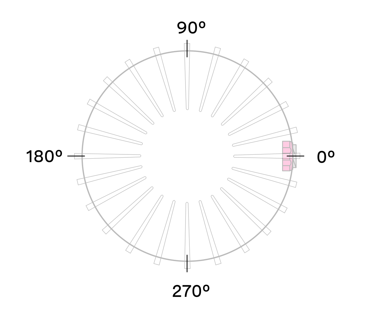
Configuring the azimuth window is a feature to only turn on the UDP lidar data within a region of interest. The region of interest is defined by a min bound and a max bound, both in millidegrees. As a reminder, angles in this frame increment counterclockwise when viewed from the top. Below is the Lidar Coordinate Frame from a top-down perspective:
0° towards the external connector
90° a quarter turn counterclockwise from the connector
180° opposite the connector
270° three quarter turns counterclockwise from the connector
Configuring the azimuth window lowers the average output data rate of the sensor but does not affect the peak output data rate of the sensor. It also does not stop the lasers from firing and thus does not have an effect on power consumption or thermals.
Expected Sensor Behavior
The sensor will round the input azimuth window bounds to the nearest Measurement Block IDs generating new ID-based bounds. The new bounds are used to mask Measurement Blocks in the lidar data packets. Lidar packets containing only masked Measurement Blocks are not output, and there may be partially masked Measurement Blocks in the two bookended lidar packets in each frame. The Measurement Block Status field will indicate the valid or masked/padded Measurement Blocks in any partially masked lidar packets. (See the Lidar Data Packet Format section for details on the lidar data format.)
The visualized output will contain jagged edges caused by the staggered, nonzero nature of the beam azimuth angles. It is necessary to set more conservative (wider) bounds to push the jagged edges beyond the desired window. This can be determined through trial and error or calculated deterministically with knowledge of the queryable beam azimuth angles.
Azimuth Window Examples
The TCP API Guide lists the command for setting an azimuth window. Below are example settings.
The command syntax is as follows:
set_config_param azimuth_window [min_bound_millidegrees, max_bound_millidegrees]
Default settings of 360° window:
set_config_param azimuth_window [0, 360000]
Set a region of interest between 0° to 180°:
set_config_param azimuth_window [0, 180000]
Set a region of interest between 270° to 90° with 180° field of view:
set_config_param azimuth_window [270000, 90000]
Set a region of interest 90° to 270° with 180° field of view:
set_config_param azimuth_window [90000, 270000]
Set a region of interest between 0° to 90° with 90° field of view:
set_config_param azimuth_window [0, 90000]
Set a region of interest 90° to 360° with 270° field of view:
set_config_param azimuth_window [90000, 0]
Standby Operating Mode
Starting with firmware v2.0.0, the sensor can be commanded in and out of a low-power Standby Operating Mode that can be useful for power, battery, or thermal-conscious applications of the sensor.
The TCP config param operating_mode has a default value of NORMAL. Setting it to STANDBY puts the sensor into Standby Operating Mode upon reinitialization.
Expected Sensor Behavior
Power draw in Standby mode 5W. The motor does not spin, and light is not visible from the window. However, the sensor is on and listening to commands. The sensor status will be STANDBY.
Standby Operating Mode Examples
Below are example netcat console command input and responses for several use cases of the Standby mode.
Note
In the examples below, to distinguish between the command and expected response, a dash has been added before the expected response. The actual response will be without the dash.
Set sensor into Standby mode and keep sensor in Standby mode upon power-up at next use:
$ nc os-991900123456 7501
set_config_param operating_mode STANDBY
-set_config_param
reinitialize
-reinitialize
save_config_params
-save_config_params
Set sensor into Standby mode but have sensor start in the default Running mode upon power-up at next use:
$ nc os-991900123456 7501
set_config_param operating_mode STANDBY
-set_config_param
reinitialize
-reinitialize
Command sensor back into Running mode and save config:
$ nc os-991900123456 7501
set_config_param operating_mode NORMAL
-set_config_param
reinitialize
-reinitialize
save_config_params
-save_config_params
Note
auto_start_flag has been deprecated with Firmware 2.4 and later. For prior Firmware versions auto_start_flag 0 is equivalent to operating_mode STANDBY and auto_start_flag 1 is equivalent to operating_mode NORMAL. Please use operating_mode wherever possible in client code.
Warning
Usage of auto_start_flag in firmware prior to v2.0.0 has unexpected behavior.
Signal Multiplier
For Gen 2 sensors with firmware v2.1 or higher, the signal_multiplier config parameter allows the user to set a multiplier for the signal strength of the sensor, which corresponds to a maximum allowable azimuth window. Lasers are disabled outside of the maximum allowable azimuth window. By default the sensor has a signal multiplier value of 1.
Use Cases
The config parameter signal_multiplier <1/2/3> sets the signal multiplier value. For 2x and 3x multipliers, the azimuth_window [int, int] parameter sets the azimuth window that the lasers will be enabled in. The higher the signal multiplier value, the smaller the maximum azimuth window can be.
Signal Multiplier Value |
Max Azimuth Window |
|---|---|
1 ( Default) |
360° |
2 |
180° |
3 |
120° |
All sensors have equivalent power draw and thermal output when operating at the max azimuth window for a particular signal multiplier value. Therefore, using an azimuth window that is smaller than the maximum allowable azimuth window with a particular signal multiplier value (excluding 1x) can reduce the power draw and thermal output of the sensor. However, while this can increase the max operating temp of the sensor, it can also degrade the performance at low temps. This discrepancy will be resolved in a future firmware. The table below outlines some example use cases.
Use Case |
|
|
|---|---|---|
Signal boost |
3 |
[0,120000] |
Signal boost with power draw reduction |
2 |
[0,90000] |
Expected Behavior
If the sensor has signal multiplier of 1, lasers will be enabled for all 360° of the window, regardless of the azimuth_window set.
If an invalid pair of signal multiplier and azimuth window values are set, the sensor will throw an error. If a valid pair of values are set, upon reinitializing, the sensor will operate in the signal multiplier mode.
Examples
The following shows the netcat console input commands and responses for some configuration examples.
Note
In the examples below, to distinguish between the command and expected response, a dash has been added before the expected response. The actual response will be without the dash.
Set sensor in 3x signal mode with 120° HFoV:
$ nc sensor1_hostname 7501
set_config_param set_config_param signal_multiplier 3
-set_config_param
set_config_param azimuth_window [120000, 240000]
-set_config_param
reinitialize
-reinitialize
save_config_params
-save_config_params
Sensor will throw an error if invalid parameters are set:
$ nc sensor1_hostname 7501
set_config_param signal_multiplier 5
-error: signal_multiplier must be between 1 and 3, inclusive
set_config_param signal_multiplier 3
-set_config_param
set_config_param azimuth_window [120000, 300000]
-set_config_param
reinitialize
-error: for signal_multiplier value of 3, azimuth_window must span a maximum of 120000 millidegrees.
        Current azimuth_window [120000, 300000] spans 180000 millidegrees.
Sensor Performance by Operating Configuration
Depending upon the sensor’s lidar mode and signal multiplier setting, the sensor performance will vary from its baseline as listed on the datasheet. This section will present the estimated performance multiplier depending on the sensor and the operating configuration.
Estimated range multiplier
When using a signal multiplier higher than 1x and depending on the lidar mode, the sensor will get a range increase. The following tables present an estimated range multiplier depending on the operating configuration.
OS0 and OS1
For the OS0 and OS1 sensors the baseline is the 1024x10 mode
Frame Rate / Horiz. Res. |
512 |
1024 |
2048 |
||||||
|---|---|---|---|---|---|---|---|---|---|
Signal multiplier |
1x |
2x |
3x |
1x |
2x |
3x |
1x |
2x |
3x |
10 Hz |
1.19 |
1.41 |
1.57 |
1.00 |
1.19 |
1.32 |
0.84 |
1.00 |
1.11 |
20 Hz |
1.00 |
1.19 |
1.32 |
0.84 |
1.00 |
1.11 |
NA |
||
OS2
For OS2 sensors the baseline is the 2048x10 mode.
Frame Rate / Horiz. Res. |
512 |
1024 |
2048 |
||||||
|---|---|---|---|---|---|---|---|---|---|
Signal multiplier |
1x |
2x |
3x |
1x |
2x |
3x |
1x |
2x |
3x |
10 Hz |
1.41 |
1.68 |
1.86 |
1.19 |
1.41 |
1.57 |
1.00 |
1.19 |
1.32 |
20 Hz |
1.19 |
1.41 |
1.57 |
1.00 |
1.19 |
1.32 |
NA |
||
Note
The values in the tables above are given for guidance only. The only specs guaranteed are the ones defined in the sensor datasheet for a specific mode.
Maximal representable range
Depending upon the signal multiplier, the maximal representable range of the sensor will be different. The table below shows the maximal representable range values for each sensor type and multiplier value.
Signal Multiplier Value |
OS0 |
OS1 |
OS2 |
|---|---|---|---|
1x |
270 m |
270 m |
465 m |
2x |
135 m |
135 m |
232 m |
3x |
90 m |
90 m |
155 m |
Range returns beyond the maximal representable range will experience range aliasing. Therefore, these modes are only recommended in scenarios where there will not be any returns beyond the maximal representable range.
Estimated precision multiplier
When using a signal multiplier higher than 1x and depending on the lidar mode, the sensor will get a precision improvement. The following tables present an estimated precision multiplier depending on the operating configuration. Please refer to the Signal Multiplier section for more details.
OS0 and OS1
Frame Rate / Horiz. Res. |
512 |
1024 |
2048 |
||||||
|---|---|---|---|---|---|---|---|---|---|
Signal multiplier |
1x |
2x |
3x |
1x |
2x |
3x |
1x |
2x |
3x |
10 Hz |
0.71 |
0.50 |
0.41 |
1.00 |
0.71 |
0.58 |
1.41 |
1.00 |
0.82 |
20 Hz |
1.00 |
0.71 |
0.58 |
1.41 |
1.00 |
0.82 |
NA |
||
OS2
Frame Rate / Horiz. Res. |
512 |
1024 |
2048 |
||||||
|---|---|---|---|---|---|---|---|---|---|
Signal multiplier |
1x |
2x |
3x |
1x |
2x |
3x |
1x |
2x |
3x |
10 Hz |
0.50 |
0.35 |
0.29 |
0.71 |
0.50 |
0.41 |
1.00 |
0.71 |
0.58 |
20 Hz |
0.71 |
0.50 |
0.41 |
1.00 |
0.71 |
0.58 |
NA |
||